Hello,
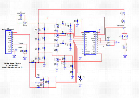
We are working on a supercap backup circuit that uses the TI BQ33100. While the EVM shows examples for a 5 cell setup, we have a 4 cell setup, and have a few questions that we can't answer using the datasheet and EVM user guide. We based most of our design off the diagram on page 11 of the datasheet, and I'll refer to those component reference designators. Also, here is my design so far.
- In the eval datasheet, there is a voltage divider using (R32) and (R33) which connects to VC5. In my design since I only have 4 caps and per the datasheet on a 4P setup, I grounded VC5 and rerouted this voltage divider output to the VC4 pin which on my sheet is R21 and R22. Did I make the right assumption?
- We only have 1 pin for power in/out of the board. Power will be provided for charging when the main supply is working, and then we provide power out when that power goes away. On the EVM, the input and output are separated on (TB1) and (J1). TB1 is separated from the circuit using (Q6) to control the charge process. In my diagram (Q6) is Q1 and in order to allow both input and output of power on the SC+ power pin, I added the shotkey diode D1 to allow controlled charging by the BQ33100, but then allow power to freely flow back to the device during a power failure. Is using that bypass diode an acceptable way to set up a single connection for both charging and discharge? Would this cause any problems that you are aware of? Do I need back to back FET's?
- Next, the 5V power supply is going to be supplied from a separate 5V source that comes in from the +VIN pin on the interface connector P4 and then gets regulated to a steady 5V using an LDO on this board. On the eval board, the power supply for the BQ33100 gets its power from the system input (TB1) which is active when the charge power is on. On my board, the BQ33100 may have power from the 5V circuit even though there is no net positive energy on the SC+ line to actually charge the caps, and instead it would be in discharge mode. Would this cause any strange behavior with the BQ33100 such as it thinking there is a charging fault or something similar?
- Finally, I am not exactly sure what to do with the CHGLVL0/1 and am not sure if I even need them since I am not using the on-board charging circuit. Do I need to do anything special with those?
Thank you,
JC


