Part Number:BQ40Z60
Hi,
I built custom PCB with BQ40Z60 based on BQ40z60EVM.
Firstly, I have problem with understanding some passages from here
A resistor cell simulator can be used instead of battery cells. Connect a resistor between each of the contacts on the J3 connector (for example, from 1N to 1P, from 1P to 2P, and so forth) until the desired number of cells has been achieved. A power supply can provide power to the cell simulator. Set the power supply to the desired cell voltage x the number of cells, and attach the ground wire to 1N and the positive wire to 4P, for example, for a 3S configuration with a 3.6-V cell voltage, set the power supply to 3 x 3.6 = 10.8 V.
It means that instead of the batteries I have connected 1k-resistors and (in my case) between the 1N and 1P terminals I connect 4*3,6 = 14.4 Volts ? And I have still connected adapter 20V ?
Because as is mentioned below in italics the adapter should be connected.
Charger supply voltage connection across VAC and PGND Attach the power supply for the charger to the J1 terminal block. Connect the positive load wire to at least one of the two terminal block positions labeled VAC. Connect the ground wire for the load to at least one of the two terminal block positions labeled PGND (see Figure 1).
So I am bit confused about connecting 2 sources against each other.
Secondly I have probelm with bqStudio.
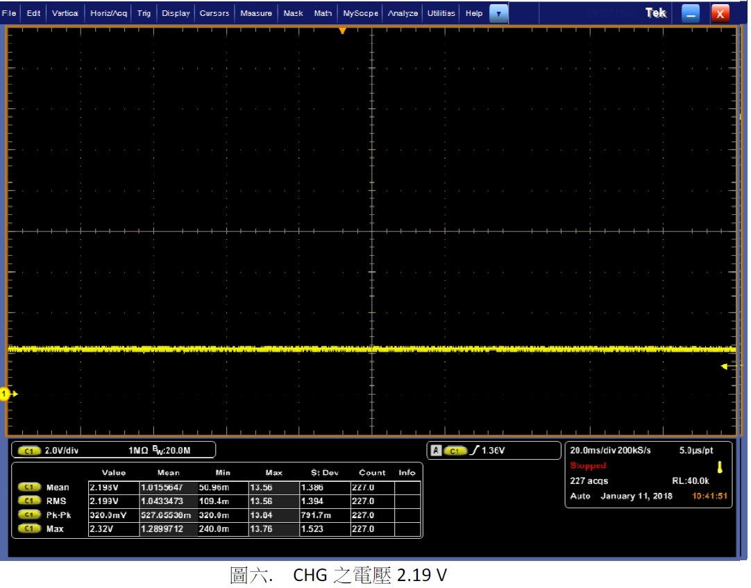
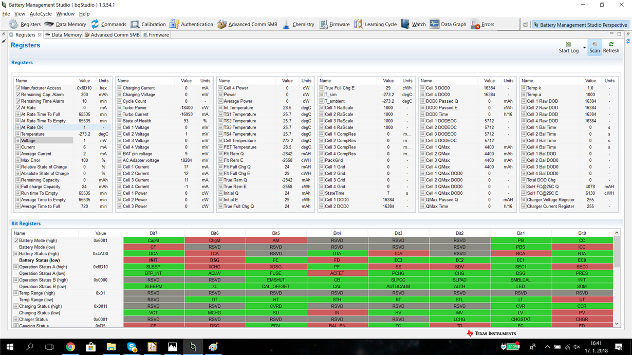
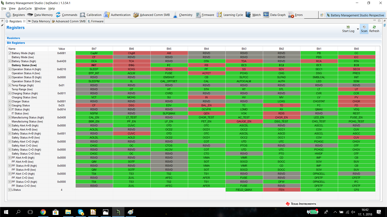
I tried to connect 3 laboratory sources with 4 Volts(instead of batteries) in series and after half a day I got my voltage from sources to OUTPUT. I tried almost everything and I don't know where exactly the problem was, but I think after turning off UTD (under temperature discharge protection) I could Turn on DSG_FET. I did that, becouse as it is shown in the picture below I measure temeprature, cell temperature and T_ambient as -273,2°C.
(I had connected 3S and 4S batteries, and I always set that in bqstudio. I dont have jumper J4, but I think it is just for charger voltage. When I am charging batteries, then I have 4S. So there the problem wasn't I think)
It could be good, if I measure some better temperature, but in fact I don't need it. I was searching that and I don't even know what it measures. It is Temperature of outside? I need just temperatures from TS1 to TS4.
So I got working that situation, when I connect batteries and I want to dischrge them. But it is a bit wierd that I have to tell bq40z60 for turning on that FET. I thought It will be automatical, and when I turn it ON, I will see voltage on the output.
Now the biggest problem for me is that, I can't make working charging process. I tried that just with resistors (without supply for them as I told Above, I am bit confused about that) and I couldn't measure voltage on the risistors.
When I sent CHG_FET_TOGGLE command, XCHG lighted green, but on Gate I didn't measure correct voltage for open that transistor. So I couldn't "manually" turn CHG FET on.
I would like to know, if ithere is any option fof automatic control. I mean that when I connect Adapter it automatically starts charging and provide Voltage on the output. Or when I dosconnect adapter It will automatically provide energy from batteries. Is it possible ? Becouse I canť find any easy solution.
Unfortunately, I lost my .srec file and becouse I am working on that in school as my bachelor thesis, I have to wait until next wednesday. So if there is possibility of finding any help without that file I would be glad.
Is there some tutorial for that or some pdf, where is it written, what should i set to make it work? I found this, but I couldn't find inside ,for example what measure Cell_Temperature or Temperature, and what is their smallest value. (I think It is -273,2). Or if Turning off Under temperature protection is enaugh for getting it work, when I measure that figures as -273,2°C.
And I probably still don't understand, what exactly thet Battery gauge should do.
I will be glad for any help.
Regards Ondrej