Quantcast
Channel: Power management forum - Recent Threads
Viewing all 35901 articles
Browse latest View live

bq40z50 Unsealed to Full Access

$
0
0

Dear all,

My bq40z50 EVM as received from TI has the Operation Status Reg A set to 0x6181 which is Unsealed mode. I want to change this to Full Access.

I have tried to follow the TRM 10.5.3 page 66 and 12.1.33 page 75 writing the two Words 0XFFFF and 0XFFFF within 4 Seconds from Manufacturer Access (register top left of Battery Management Studio) but With no sucess. After a lot of trials I still read 0x6181

I am pretty sure I am doing something wrong and after a lot of trials I rather ask the Forum for help

Any comments from those who knows how to do ut will be much apprciated

Best regards

Kjell


Battery protection IC for 4-series application

$
0
0

Hi All,

Now I'm looking for the battery protection IC for 4-series application which has following function.

[Requirement]

  • 4-series
  • OVP (Over Voltage Protection)
  • UVP (Under Voltage Protection)
  • OCP (Over Current Protection)
  • SCD (Short Circuit Protection)
  • Temperature monitoring
  • Indication of error condition by LED
  • Standalone

I confirmed the bq77908A can  correspond these requirements except LED support. I also confirmed bq40z50 can correspond them included LED support, but it may be overspecified because they don't need gauging...

So I'd like to have your advice about the suitable solution for this requirements.


Your advice will be appreciated.


Best Regards,

Sonoki / Japan Disty

bq34z100 and ev3200 communication error during battery charging

$
0
0

Hello,

I am developing a 8 cell LiFePo4 battery pack using the bq34z100 evaluation module and are communicating with it over I2C using the EV2300 USB - I2C converter. The only modification I have made to the EVM is to replace the sense resistor with a 2 mOhm resistor to support a charge/discharge current of 15A. I believe I have configured the data flash correctly but I am new to this process so it is possible that I have made a mistake.

The problem which I am experiencing is that the communication fails while the battery is being charged. If I try to read the flash I get an error code of 772. The communication link works fine while the battery is discharging or while the charger is connected but not charging (the battery is full).

I found another post which suggested that the lack of I2C pullup resistors in the EV2300 may be the cause, however, adding a 10k pullup to Vcc did not change the behavior in any way.

Are you able to suggest a possible cause? Is there any information I can supply or tests I can perform which would assist in diagnosing this problem?

Thanks

Michael

BQ34Z100PW - SW1 and Rt1

$
0
0

From the example of 1-Cell Li-Ion, I am not sure about the function of RT1 and SW1. Can any one tell me if I remove this features, then what is the effect?

I guess the SW1 is to turn off the LED display to save energy. But I am not sure what is RT1 for. Can anyone help?

Thanks!

Missing definition ReadSMBusByteArray and WriteSMBUsByteArray and WriteSMBuSCommand

$
0
0

Hello everyone,

i would like to read and write data flash to make golden pack.


i am using a raspberry pi to do that, i translate the VB code (slu379E) in C code but i have a probleme with 2 SMBus function.

WriteSMBusByteArray

WriteSMBusCommand


Where i can found this c code or vb code?

Thanks in advance for your help

Bad capacity prediction and rough temperature/current correction with bq34z100

$
0
0

Hello.

I trying use bq34z100 with 4-parallel NCR18650 Panasonic (2900ma) battery set, but after testing got very bad results. Please check my records, maybe you can give me recommendation for improving working with this ICs.

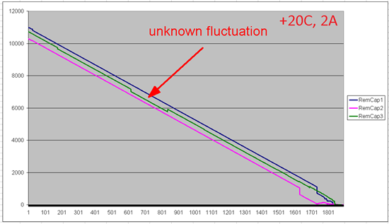
At first I set config for my battery specification and received golden image (file "config.gg"). Here three graphs of Remaining Capacity prediction in calibration progress when discharging (graph1).

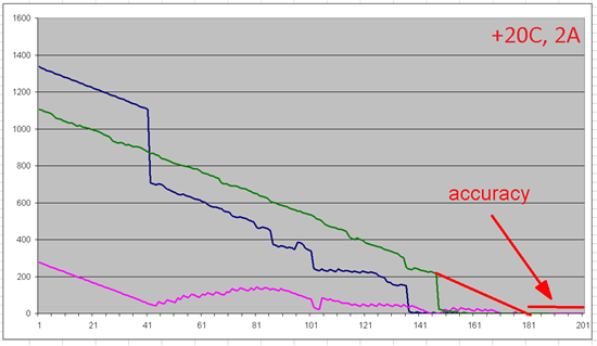
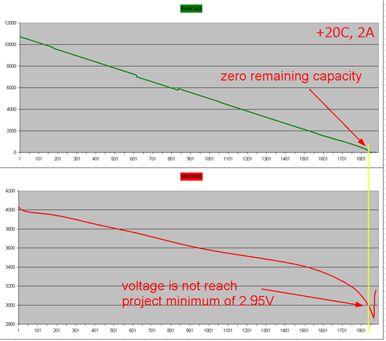
As you can see, the last (3) curve has a very good precision, if draw a line for the end (graph2 is zooming) we get about 1.1% accuracy in overall. But shape of the graph is not very good for real use, because it have unknown step-fluctuation (with sharp jumping of % capacity about 2%, see graph1). Besides, prediction capacity is over before voltage reached minimal value. Please see graph3 with end of third calibration curve with imposed voltage curve. As I understand, prediction capacity must be related with current voltage according chemical table (for my type of battery NCR18650, wich be uploaded before calibration), but correction too juddering, even it is.

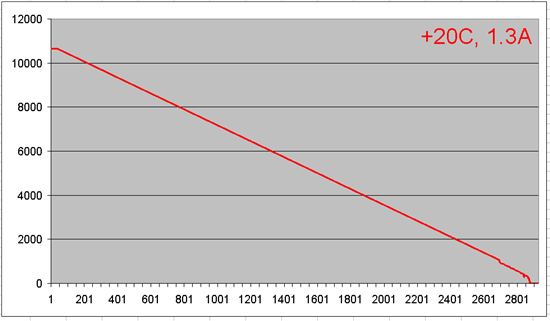
Here measurements on a less current ~1.3A, results not bad (see graph4), exept step-down at the end.

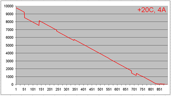
Here measurements on a larger current ~4A (see graph5), and results not very good - curve of remaining capacity prediction fall down on about 9% earlier of real capacity. And again we see a several big step-fluctuation (as I understand this is may be a fault of comparing with chemical table).

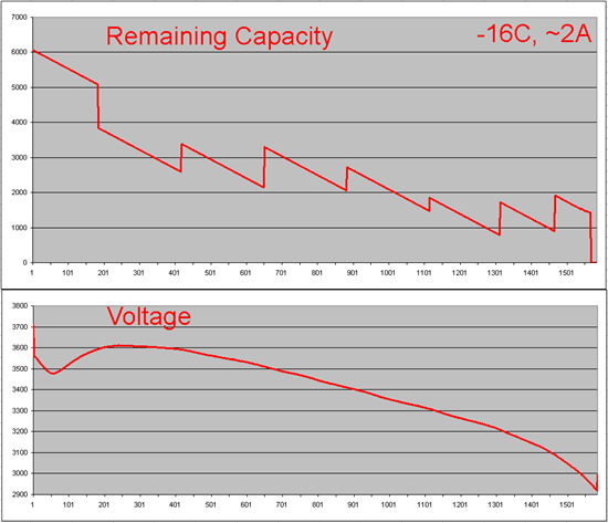
And next battery prediction testing at different from calibrated temperature on about -16C. Results very poor. (see graph 6) Curve has giant steps without any correlation with real capacity.

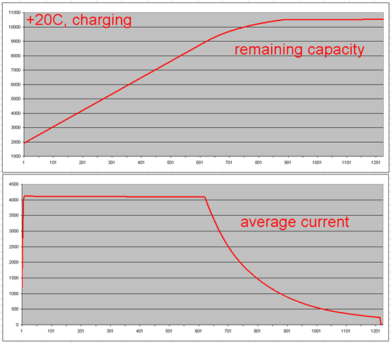
However, once I noticed, that counting on charging is not work correctly at the end of charge. Capacity counting just stops on certain value and not count some % of energy. Its happend while charging battery after it was fully discharged at -16C temperature, then heated by the room temperature with restoring remaining capacity to about 2000ma. See graph7.


So, as I see capacity prediction is not work correctly, but cant find reason for this.

Q1. Whether it is possible smoothing graph of remaining capacity prediction to eliminate step-correction of prediction?
Q2. Is it possible eliminate graph break at the end and strech it according minimal voltage value?
Q3. How to reach good working bq34z100 with my battery on terms different from first calibration (20C, 2A)?
Q4. Why there was a failure of capacity counting on charging?

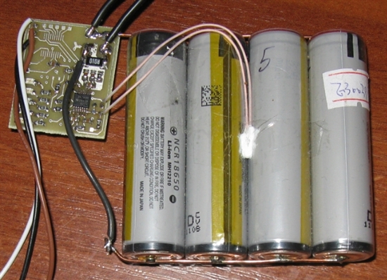
PS: Im sure that chemical of my battery is the same as I choose in chemical selection list (NCR18650 2900ma code 0238), temperature probe has good thermal contact with battery, was placed between nearby elements and is correctly type (103AT 3435K), all elements brand-new and fresh. I attach photo of my testing setup and full log in four files of all my tests.

I will be grateful for any advice.

With best regards, Viktor.

(Please visit the site to view this file)

(Please visit the site to view this file)

(Please visit the site to view this file)

(Please visit the site to view this file)

(Please visit the site to view this file)

GNDSEL bit in OCR BQ27501

$
0
0

Where could I find more information about the use of the GNDSEL bit in the bq27501? In the specification SLUS879A - June 2009 I find I think some confusing information.

In chapter 5.3.1 I can read : GNDSEL = ADC ground selection control. The Vss (Pin 6) is selected as the ground referenced when the bit is clear. Pin 7 is selected when the bit is set. Default = 1.

In chpater 4.6 DATA FLASH SUMMARY I can read: Operation Configuration Default Value 0x0979.

This tells that bit GNDSEL = 0 by default.

What is correct? What is the real use of GNDSEL?

LMD register in bq2013h

$
0
0

hello, everyone

i am using bq2013h IC to gauge 2300 mAh Ni-Cd Battery. I encounter the following problem:

in bq2013h, LMD register is 8bits. So this IC only can measure maximum of 256mAh. isn't it?

Also in bq2013h datasheet I see NAC=LMD while NAC register is 16bits. Why so? I don't understand that.

please to explain that to me.

thank you very much!


About BQ2013H initialization and NAC register

$
0
0

Hello, Mr. 
Recently, I also learn BQ2013H chip, experiencing some of the following questions, please give me your answer: 
1 NAC register on the issue, I would like to read the NAC (available capacity registers) by which the value of simple microcontroller to accurately display the power, but the problem is I do not know how to read out the data is converted into electricity that I want data? 
2 About BQ2013H initialization problem, I tried many methods, but without success, it seems there is no talk of a detailed user manual. 
These are my questions, looking to get your answer. Thank you.

I2C/SMBus commands for bq40z50

$
0
0

Hi community,

I wanted to know about how to fetch data from the bq40z50 with I2C commands.

At first, most important for me is, which slave address the bq40z50 has, to be addressed by a microcontroller. I didn't find this in any data sheet i searched in.

The second question is how to use the commands, to fetch data by microcontroller without using the EVM. What is the sequence of bytes which are send/read to or from the bq40z50. How can I send 2byte commands on a bus system with only one byte messages, are the 2 bytes directly send after each other and which is first? Can you please explain to me the sequence of bytes in an example (let's say reading out the temperature

0x08 Temperature() - This read word function returns the temperature in units 0.1°K).

How does the Block command (for example ManufacturerAccess() 0x0071 DAStatus1) work, what is there the sequence of bytes? is there an Acknowledge between each byte?

I hope you'll be able to help me.

Kind regards and thanks,

Benjamin Geirhos

problem with bq27530 on new layout

$
0
0

HI

we have manufactured a pcb with the bq27530 and bq24161 connected to it directly as in the evl.

we are connecting to the bq27530 via ev2300 just like the evl. we have managed to upload the exported gg file from the evl to the new layout.

the problem that instantly can be noticed is that the gaugestudio shows that the temperature is 280 deg.

my question does the calibration of the evl is also uploaded or that it need to be calibrate again. we think it should be calibrated again but does such high temp can show that there might be a problem (all the resistors on the TS line are correct )?

when we tried to calibrate or change any parameter via the ev2300 using the gaugestudio the log show that there is a problem writing to the flash and the data was not changed (after we hit fully unseal) why is it happening? what else should we do in order to write on the flash?

please help us ASAP we are stuck with a component that doesn't work on our layout. 

thanks in advanced

bq34z100 difficulty in achieving a learning cycle

$
0
0

I am attempting to perform a learning cycle on a 1p8s 15Ah LiFePO4 pack of headway cells but am not able to get the FC bit to set and thus progress to 0x05 in the IT flags.


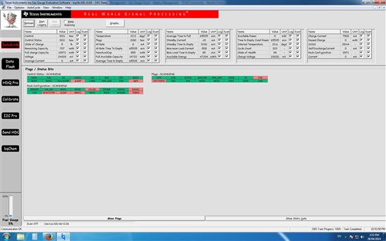
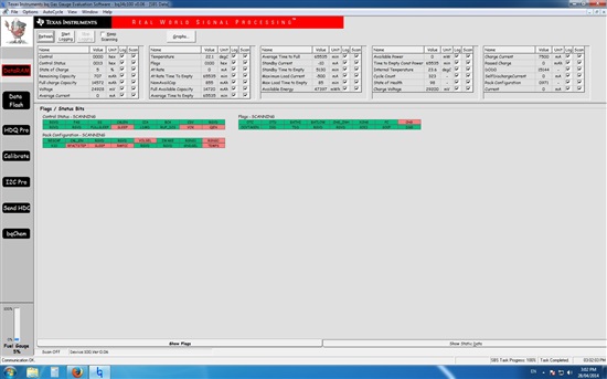
Attached are screenshots of the RAM after clearing the IT flag, sending a reset command (0x41) and then resting,

as well as, immediately after enabling IT (command 0x21).

Also attached is the gg file of the flash before and after enabling IT.

(Please visit the site to view this file)

(Please visit the site to view this file)

Can you please have a look to see if there is any parameters which I have not set correctly. I have not been able to find any solutions on the forums which seem to work for me.

Some things to note about the system: I am using the EVM but have changed the sense resistor to 2 mohm to facilitate a higher current operation. The charger I am using charges at about 6.8A and cuts off when the current draw falls below approximately 450mA.

I am currently logging data during a charging cycle and can post it when it is done if it is helpful.

Thanks


Edit: also attached is the log file of the charge

(Please visit the site to view this file)

BQ783xx

$
0
0

Hello,

In the BQ76920 datasheet a Companion Controller IC BQ783xx  is mentioned.

I cannot find this product family (BQ783xx) in the catalogue.

Please provide a link to the aforementioned device.

Thanks!

hw version bq27530

$
0
0

Hi

in our great effort to understand the problem with the bq27530 which doent write to the flash we found out that our hw version is A8 and in the evl it is A7. why are they not the same? what is the difference between versions????

is there a reg that need to be change in order to allow flash write?

can calibration be done if falsely feels 170 deg? 

Regards,


BQ27421-G1 configuration Issue

$
0
0

Hello,


I'm trying to change some parameters on the BQ-27421-G1A but I'm always have an error.

I want to change Battery capacity, TCA parameters (clear set), FCC parameters, SOC1 parameters, SOCF parameters, design capacity, design energy.

I tried the command in the technical documentation chapter "Data Memory Parameter Update Example".

I also tried to send the command in the dffs file.

The problem is with the checksum. The module doesn't answer. I have an error each time.

I don't understand why.

What is the way to change parameters.

Can you help me?

Can you please tell me which command I have to send? At which baudrate (I'm usign 400kHz and I tried 128kHz).

Regards

Guillaume


bq76PL536EVM-3 Packing List

$
0
0
Hello,
 
I would like to know latest packing list of bq76PL536EVM-3.
Below is the Packing list from SLUU437B.
However, there is no CD-ROM in EVM.
Could you please let me know the latest packing list ?


Best Regards,
Ryuji Asaka

bq2084-V143 ???

$
0
0

Hi,

I use a bq2084-V143 with a bq29312a with 4 li ion cells...

I don't have the evaluation board... I have my own PCB and I communicate with the bq2084 over SMBUS (I2C on an Atmel µC)

I'm able to read the register on the Table 3 of the datasheet and the values are right (these are the default values), like FullChargeCapacity = 0x1c20 = 7200mAh, the VCELLs etc...

First, I want change these values for my batteries (4Cells 2600mAh in serie)

Second, When I read the RemainingCapacity (0x0f) the register is all the time equals to 0x0000. and when I push my press button for display RemainingCapacity with the 5 Leds, The first led is blinking (I think's it's normal because the register say the RemainingCapacity is 0).

What do I need to do??? to configure??? Thanks and sorry for my bad English ^^

bq27500 Flash Parameters Conversion & Write

$
0
0

Hello,

I have a few questions regarding the data flash parameter conversions in the bq27500.  I have already run the bqEasy process and obtained the new, updated values from the entire process. Because our gauge is embedded in our system and is talking to a microcontroller it is more efficient for us to write the values to the gauge using the commands instead of flashing the entire DFI to the chip.  

My question is twofold.

1. Are the values that were taken from the data flash tab in bqEasy converted correctly? We used the pdf found on the TI website to do the conversions.

CC Gain = 12.705 =  0x7FC02566   CC Delta = 12.652 =  0x93DB1C60

CC Offset = -0.101 =   0x2E                Board Offset = -0.4 =       0xFF2E      

2. Is the way in which we're writing the values to the gauge in the attached .ini file the correct way to write the values to be persistent in the flash data? Like I said before, writing the entire .DFI to the gauge is not a feasible option for us, so being able to change these values by sending commands is the only solution.

Please let me know if you need more information in order to help. 

bq27531 - Which Gauge Studio parameters change when you select a Chem ID?

$
0
0

Hello,

I've loaded the 3102 Chem ID into the bq27531 via GaugeStudio, however I do not agree with some of the parameters in the Data Memory window. Most importantly, Charging Voltage (4.2V) and Design Capacity(2450mAh).

The LG cell that matches ChemID 3102 is only 2100mAh on a good day, and should float at 4.35V.

Which parameters in the Data Memory window will change upon loading a new ChemID? Meaning, how much does the user need to enter from the cell datasheet?

Thanks

bq29209 cell balancer

$
0
0

I am having a problem understanding the cell balancing IC datasheet. specifically the Recommended Cell Balancing Configuration table listed on page 5 of the datasheet. It lists the ICB values with a specified RCB value from the table. It then goes on to show formulas for ICB1 and ICB2 but i cant seem to work backwards to get the values listed in the table. Is there some other formula missing?

Also in the Customer test mode section it states you enter this state by having VDD set to 9.5v above VC2 but in the application circuit it has VC2 tied thru a resistor to VDD. Do you have more information on the CTM mode? I assume i do this with the batteries disconnected. Thanks.

Viewing all 35901 articles
Browse latest View live


<script src="https://jsc.adskeeper.com/r/s/rssing.com.1596347.js" async> </script>