Quantcast
Channel: Power management forum - Recent Threads
Viewing all 35901 articles
Browse latest View live

Latest Battery Management Studio software (Rev. C)

$
0
0

I could never get the Battery Management Studio software Rev B to recognize the EV2300 on my (Win7 Enterprise, 32-bit PC), so I had hopes that it would with Rev C. It installed correctly, but I get this error at start up (see attachment).

Strange thing is that I get this error regardless of whether the EV2300 is connected or not.

Any thoughts on how to troubleshoot this? I'm tired of using a second PC just to talk to the EV2300 (and we don't want to buy an EV2400!)

tom


BQ24032A decoupling

$
0
0

Hi,

Q1: Do I need any decoupling on the LDO output (PIN1) if I do not use it?

Q2: Do I need any decoupling on the USB input (PIN20) if I use AC input (PIN4) only?

thanks for help.

best regards

Ben

BQ Evaluation Software : Modifying Data Flash using GUI

$
0
0

Hi  ,

I am using the BQ34Z100 EVM with BQ Evaluation S/W , I am able to write to Control() from the data RAM screen but can't modify the Data Flash Contents , The following are the steps i took to modify data flash ,

To Modify Device Name : 

Default Value :bq34z100

Change to : aaa

1>>Click "Read All " button ,then click on the Device name and edit to "aaa"

2>>Press Enter (When i do press enter the default value appears back in red in the same place)

3>>Press Write all Button ,the DF task progress goes from 0-100% 2 times and writes flash ,but i'm not able to change any value in the DF screen

Please provide a solution ASAP.

Best Regards

Abhay


Need help with bq20z75 v160 senc file

$
0
0

I am having issues with extracting a Golden .dfi from a pack equipped with V160. (The low volume of this project requires an off-the-shelf board; this is how the mfr. supplied the boards for testing.)

  • bq Software auto-selected V1.60 when connected to the pack

  • I cycled the pack to set the RA tables and saved the .data flash file 

  • I set the gg to ROM mode and programmed the V1.81 Senc

    • I saw multiple places in these forums that the files were compatible.

    • After the load was complete, the eval software advised to restart before loading the data flash to prevent damage to the IC (something to that effect).

    • I sent the command to exit ROM mode and exited the eval software

  • I restarted the eval software, which now auto-selected V1.81, but gave errors when trying to open the Data Flash file

    • Several parameters were reports as missing while opening the file

    • I also noticed the OCV table tab was not available in the Data Flash window

    • I did a little deeper digging and finally found a V1.60 senc file on the forum. I loaded the V1.60 senc file and now the board is totally dead - no response to the eval package at all.


  1. Can there possibly be a hardware issue if this mfr is using old stock IC’s?

  2. Is there any way to recover this pack?

  3. I have another pack I can cycle; what do I need to do to get a golden file from it?

Thanks,

Larry

Bq34z110 chemical ID for Lead Acid AGM, deep cycle type

$
0
0

Hi,

I currently have a project that involves a 12V lead acid battery pack (2 batteries, 100Ah each connected in parellel) that has a combined capacity of 200Ah. The particular lead acid type for this pack is a AGM type (Glass mat, valve regulated, 6 series cell), deep cycle.

I have downloaded bq evaluation software, ran a chemical update tool from TI to get the latest chemical IDs.

However, looking at the excel sheet provided, it seems that no lead acid batteries of the AGM variance have been characterized. Below is a snippet of it:

Chemical IDKnown compatible cellsCommentstatus, 0 if OK, 1 if NRND
0800Leoch: Valve Regulated 6s (7200 Ah)1
0801EnerSys: Cyclon DT (4500)1
0802Panasonic: R121R3P1
0803Panasonic: LC_P1220P, Enersys: Cyclone_D (2500mAh)0
0804Sonnenschien: A512 (10A)0
0805Exide: FX10_12XT9_8 (10Ah)0
0806Bazooka: HPT-150 (150Ah)CONTACT TI BEFORE USING THIS ID0
0807US.Battery: XTREME_Capacity (155Ah)0

Since chemical ID 0800- 0802 are not recommended for new designs (NDRD), I am not considering them.

As for the rest of the chemicals, the closest match is the Sonnenschien: A512 (10A), which is a deep cycle gel battery. The panasonic P1220P is meant for UPS applications and not for deep cycle discharge in my opinion.

I have heard of a mathcad program that will help the engineer to choose the closest chemical ID and I will go an attempt to do that.

I have two questions:

1) Is there any updated chemical ID library that has more batteries that are characterized? Any timeline of any newer version?

2) Why are chemical IDs 0800- 0802 flagged as NRND ?

I have searched the forums and most of the posts are related to the Litnium Ion battery chemistry.
bq34z100 difficulty in achieving a learning cycle

$
0
0

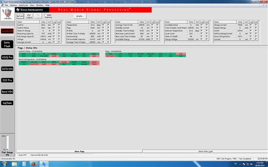
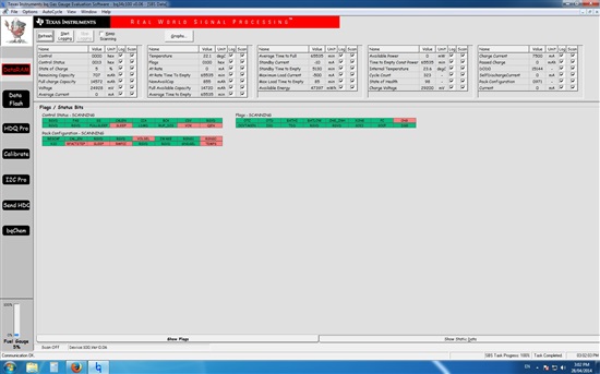
I am attempting to perform a learning cycle on a 1p8s 15Ah LiFePO4 pack of headway cells but am not able to get the FC bit to set and thus progress to 0x05 in the IT flags.


Attached are screenshots of the RAM after clearing the IT flag, sending a reset command (0x41) and then resting,

as well as, immediately after enabling IT (command 0x21).

Also attached is the gg file of the flash before and after enabling IT.

(Please visit the site to view this file)

(Please visit the site to view this file)

Can you please have a look to see if there is any parameters which I have not set correctly. I have not been able to find any solutions on the forums which seem to work for me.

Some things to note about the system: I am using the EVM but have changed the sense resistor to 2 mohm to facilitate a higher current operation. The charger I am using charges at about 6.8A and cuts off when the current draw falls below approximately 450mA.

I am currently logging data during a charging cycle and can post it when it is done if it is helpful.

Thanks


Edit: also attached is the log file of the charge

(Please visit the site to view this file)

BQ20Z95 LED display influences current and voltage measuring

$
0
0

I'm designing battery power source using BQ20Z95 gauge.
I decided to utilize LED display and corresponding button.
Suddenly I witnessed very strange issue - when I press the LED display activation button, cell voltages and pack current measured by BQ20Z95 become wrong.

This is what I have:
Assume neither charger, nor load are connected.
Pack current is 0. Pack voltage is 16580mV.
Cell voltages are 4150, 4134, 4142, 4154 mV.

Then I toggle the button, leds light up and here it goes -pack current shown in bqEasy jumps to 2000mA, cell voltages go up to about 4300mV, pack voltage goes up to 17500 mV, then it slowly decreases to the initial point.
Of course I checked real voltages with multimeter, they stay unchanged.

All these things happen only while LEDs are glowing.
I tried to desolder LEDs one by one to find out their impact on the bug.
It appears the issue is related to the number of LEDs - more LEDs present make voltages jump higher and vice versa.

The biggest problem is voltage jumps may lead to protection failures, all kind of them, both first and second level. When the battery is alomost at full charge, measured wrong cell votage naturally may go above the safety limit of 4.25, which will lead to chip safety blocking.

My design was created on the basis of datasheet reference scematics, please see schematics attached.

Please advise.
Thanks.

Bq34z100 Control and Block commands

$
0
0

Hi ,

I wanted to know about how control command and its subsequent 2byte sub commands retrieve data.

We are considering a code  to send command 1 byte at a time to fetch the data.

So if suppose i want to fetch 'Instantaneous Current' (measured by the gauge),  send totally 4 bytes of command byte by byte in a row?

If so, i ll have to send bytes 0x00 and 0x01( control - command pair) and then send sub command (0x0018 for current)  0x00  first is used to retrieve the least significant byte of current and command 0x18 next  is used to retrieve the most significant byte.. Is that how it is?

Also, it would be great if u could tell me how available block commands ( Device Name, Manufacturer name, Device Chemistry) retrieve data.

Please help me with clarity on these as soon as possible, i am running out of time. 

Regards and Thanks,

Shamanth D R


bq34z100evm mesuring current in noisy envirement

$
0
0

Hello


I

am trying to measure the current coming from a RC LiPo charger with the bq34z100evm board.

If I use a stabilized power supply and a Fluke amp-meter and adjust the current to 500mA showing on the amp-meter the bqEVSW software shows 500mA. If I use the RC LiPo charger adjust it to 500mA, the Fluke amp-meter shows 500mA but then the bq34z100evm board reads only about 400mA. If I use the same setting with the LiPo charger on a bq20z45evm board I see 500mA with the bqEVSW software.

Do you have any suggestions why the bq34z100evm reads a 25% smaller current with the RC LiPo charger than with the stabilized power supply.


Regards Fabian

bq20z65 vs. bq20z655: Differences?

$
0
0

Just wondering if anyone knew the exact differences between the bq20z65 and the newly released bq20z655?

So far these are the differences I've found:

  • The bq20z655 is able to drive 3, 4, or 5-segment LCD (bar-graph) displays (as well as multiple single LEDs) to display battery pack conditions: "The LCD is operational at all times except when the bq20z655 is in shutdown mode"
  • The two unused pins of the bq20z65 (12 & 19) are now used by the bq20z655:

Pin 12 (COM/TP): Output / open drain: LCD common connection

Pin 19 (CE): A logical high on this pin only affects the normal operation on the charge FET when the battery is in charge/relax mode. For a logic low, the normal bq20z655 firmware controls the charge FET.


It looks like the chips are practically pin-to-pin compatible though...

Are there any significant internal operational differences between the two?

I'd appreciate if anyone could shed some light on this new gas gauge - thanks!


bq27541-g1 with primary battery

$
0
0

Hi,

I'm looking for a gas gauge to use with primary batteries, and the only one active from TI is bq2052...

But there's also the application note for bq27200 (SLUA367) that says bq27200 can be used with primary batteries.

My question is: does this apply for the newer gas gauges as well? can I use bq27541-G1 with primary batteries and the right configurations?

att.

Diogo Furukawa

bq27510 and I2C repeated start

$
0
0

I've been working on a program to read cell state from the bq27510 gas gauge on a Fuel Tank Boosterpack. I'm using the boosterpack with an MSP-EXP430G2 launchpad and currently I'm keeping the I2C clock frequency below 50kHz.

After getting the basic I2C communications working for individual read and write commands I looked into building longer command sequences. Using incremental read I can successfully get the returned values for a series of consecutive commands (eg 0x04 through 0x0B inclusive) in a single I2C packet. The incremental read sequence uses a repeated start to switch from write to read mode, and that works fine in this case.

Next I tried to use another repeated start to chain together accesses to non-consecutive commands in a single packet. I was surprised to find that the gas gauge rejected this. Here are the sequences I tried, as captured by a logic analyser:

[Master]{Slave}

[S] [0xAA]{A}[0x02]{A}[Sr] [0xAB]{A} {0X00}[A]{0x00}[N] [Sr] [0xAA]{A}[0x10]{N} ...

[S] [0xAA]{A}[0x10]{A}[Sr] [0xAB]{A} {0X6C}[A]{0x04}[N] [Sr] [0xAA]{A}[0x02]{N} ...

I reversed the order of the commands in the second attempt to confirm that the issue wasn't specific to command 0x10. In both cases the gauge responded with a NACK when I tried to write the second command.

Does the bq27510 support this use of repeated start, or does it require a stop condition between the two commands if they're not consecutive?

LiPo 7.4V battery pack fuel gauge

$
0
0

Hello,

  I need a fuel gauge for a 7.4V 6000mAh LiPo pack with built in protection (Tenergy #31185).

Any thoughts or suggestions?

Thank you for your time and help.

A

Saving .senc files

$
0
0

Just some background information:


-Using bq20z65-R1

-Using EV2400

-Using WinXp and/or Win7


Under the Pro screen of bqEVSW, you can select "Flash Memory" then "Read to File". This option is used to take read the data out fo flash and save it into a .senc file. I need to do this because, I think I bricked one of my chips by loading incorrect firmware and I'm trying to revert it to a previous version. In order to save the .senc file, the device must be in ROM mode. I write the word 0x0F00 to command 0x00 from the Pro screen, and it succesfully enters ROM mode. However, after clicking read to file, I get an error reading:

"Error in reading flash: VB_UNKNOWN Flash content may be incomplete."

After accepting this error, a second screen appears "Error reading flash! Error code (decimal)= 100"

How can I succesfully create a .senc file using the EV2400.

Visual C++ '*sample code' for EV2300 customer kit

$
0
0

 Hello  I'm Dennis who supports Samsung computer division for charger products as FAE in TI Korea.

I see provided EV2300 customer kit example code(Visual basic) in this community but my customer wants to find VC code for communication to EV2300.   *sample code means  head file(*.h) & dll which defines Init, read/write etc  functions to interface with EV2300. 

could you anyone please support this request?   my email address is  dennis.oh@ti.com   

Great thanks in adv.   


BQEasy command line

$
0
0

Hi, I am using bqeasy to talk to a bq27510 and I can successfully read and write the data flash.  I have exported the data flash and can successfully import it.  Now, I would like to do this in an automated fashion.  Is there a command line interface to bqeasy?  Or is there a similar tool that does have a command line interface?  I would like to connect to a device and export a stored data flash file, then "write all" without having to click the buttons.  Thanks for the help.

BQ76925 absolute maximum ratings - exceeded by design?

$
0
0

Hello TI Gas Gauge experts-

We are using the BQ26925 is a design and would like to take advantage of the open cell detect feature. On page 17 of the data sheet it says "In a normal system, closing a cell balancing FET will cause 2 cell voltages to appear across one cell input." This is up to 8.4V, well in excess of the absolute maximum rating of 6xn at VC1 (6V) given on sheet 4 for cell input range.

What's up with that?  It seems like we are exceeding the rating of the device, just like the data sheet tells us to!

Thanks in advance for clearing this up, and Best Regards,

-Tim Starr on behalf of BA@IW

8-cell LiFePO4 protection and monitor

$
0
0

Hi,

We are building an 8-cell LiFePO4 battery and I am tasked with the monitoring and protection of the cells. I have been considering bq34z100 in combination with bq77908a. The combination would be ideal if the host could ask the ba77908a what the individual cell voltages are, but this is not possible, is it? Is there an alternative to bq77908a or to the combination I mentioned?

EV2300 Driver WinXP

$
0
0

I am unsuccessfully trying to install the drivers for the EV2300 USB interface board.

I am using Windows XP SP3, 32 bit, I have tried both the drivers on the provided CD and the latest driver from the product page. They both install ok but when plugging the device in it does not pick up the driver.

If I point it to the folder where the installation places the files, C:\WINDOWS\TI\USB1 or C:\WINDOWS\TI\USB2, it does not pick up the driver. In device manager it appears under Other Devices as USB Device.

I have installed as administrator, tried removing drivers and reinstalling, plugging in before and after installation. Nothing is working.

bq27500 Measuring 0 Voltage

$
0
0

I'm attempting to run through the bqEasy calibration routine for a bq27500 v1.08.  I'm using the EVM board and an EV2400 to connect to my computer.  Unfortunately, when I get to the 'Calibrate' section I'm unable to run the voltage calibration.  The board always reports the measured voltage as 0mV (on the DataRAM panel as well).  When I run the calibration, I get the error message 'Calibration Failed! Error code = 5024', which I understand means 'Voltage too large (Overflow) in firmware'.  

I have tried this with the board connected to a battery pack through the J8 connector (which I confirmed is charged with a multimeter), both with and without a charger connected to the charger +/- pins.

Does anyone know why the voltage would be reported as 0, and how I can correct this so I can finish the calibration?

Thanks,

Nick

Viewing all 35901 articles
Browse latest View live


<script src="https://jsc.adskeeper.com/r/s/rssing.com.1596347.js" async> </script>