Quantcast
Channel: Power management forum - Recent Threads
Viewing all 35901 articles
Browse latest View live

LMZM33602: Excessive heat from dc-dc buck converter nowhere near maximum load

$
0
0

Part Number:LMZM33602

Hello,

I have integrated the mentioned DC-DC power supply into a board. However upon booting it up I've noticed it gets fairly hot to the touch while the load is barely 500mA @ 5V. Is this normal for this particular chip or is there something wrong in the design?

I've attached the schematic used. The chip that is being used is the 2A version, not the 3A like the schematic suggests.

Frank

TLV760: TLV76701DRVR Fixed output available ?

$
0
0

Part Number:TLV760

Hi,

I'm very interested in TLV767 to use it as a 5V input, 3.3V output regulator. In the datasheet a fixed output version is mentioned for pinout and characteristics but there is no references for this version and it don'ts seems available yet.

And references : TLV76701DRVR and TLV76701DRVT are not specified with fixed nor adjustable output. I suppose those references are only for adjustable output ?

Can you tell me when fixed output are scheduled to be released ?

PS: For my application  a 180°C thermal shutdown is very nice ! It's not easy to  LDO that don't turn off close to 150°C in this package.

Thank you.

TPS92512HV: How to bleed off output capacitor quickly when device is powered off?

$
0
0

Part Number:TPS92512HV

Using an LED string of 12 LEDs, with a forward voltage of 3.15V (Vout = 38.1V), at a certain point the LEDs don't conduct and there is a large amount of charge in the output capacitor.  Is there a way to use a bleed off resistor in parallel with the output capacitor or from Vout to GND to allow for the capacitor to bleed off its charge after the IC is powered off WITHOUT ruining the LED ripple current or regulation capability?

TPS2663: Availability of TPS2663

TPS63020: transition between Buck->Buck-Boost mode

$
0
0

Part Number:TPS63020

Hi expert,

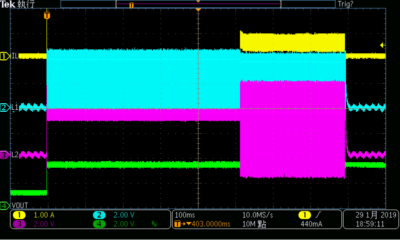
My customer found out some question on TPS63020, 4V->3.3V condition. They tested this circuit on and off and found out TPS63020 will change from Buck mode to Buck-Boost mode at one time enable is on, result is shown below. We would like to know the transition mechanism between Buck-> Buck-Boost to figure out why it would change to Buck-Boost mode. Would you kindly help on this case? Thanks a lot!!

Best regards,

Ann Lien

TPS63070: Constant Regulator output voltage and current from LiPo Battery

$
0
0

Part Number:TPS63070

Dear TI,

I am looking for a Buck/Boost Regulator that able to output 5V and 1A. The source of the power is from 2 cell LiPo 7.4V. The battery fully charged Voltage is 8.4V and start to discharge to cut-off Voltage of approximately 3V. So I need a regulator that able to output 5V and 1A for the entire discharge.

WeBench recommended TPS63070RNMR, and below is the circuit from WeBench. I have looked at the datasheet and seems good to me, but need a second opinion.

Questions are,

1. Is this chip able to support LiPo and output 5V and 1A?

2. Is this below circuit is good to go for initial stage?

BRgds

Manimaran

Help to find PWM controllers and other parts for push/pull DC/DC converter

$
0
0

Hello,

My project is a 1kW high efficiency, 12 V DC to 230 V AC converter.
My present question only concerns the 1st stage which is a step-up stage with following characteristics :

  • transformer used in push-pull topology
  • 10 V DC < Vin < 18 V DC
  • I in max = 110 A
  • Vout = 350 V DC
  • I out max = 3.2 A
  • frequ. = 100 kHz
  • High efficiency
  • not overpriced

I would like to find the right PWM controller but there's a lot of part nums ! Here are the ones which satisfy my Vin and frequency constraints :

The controller must tune the ratio according to Vout and primary current.
For current sensing, I still don't know if I will use a resistive shunt or a hall effect sensor. I'm open to suggestions.

To switch primary coils, I think to use 2 parallels MOS FET IRFP7430 (Qg=300nC , Rdson=1mOhm) on each branch (also open to suggestions).
If I use a 2A gate driver, it gives me a 0.6µs theorical opening/closing time. Any idea if it is enough (considering the 10µs period) ?
If it is good, I can choose a PWM controller with 2A drivers, if not, I can choose small ones and add external drivers.

Also perhaps 1st prototype will use standard diode rectifier, but for future efficiency improvements, I would prefer to use mosfet rectifier ready components (i.e. a pwm controller with sync output pin).

So, the main questions are : Which PWM controller do you recommend ? And is there useful surrounding components ?

Any advice is welcome.

Thank you.

Adrien

TPS65133: -5 V inverting buck boost converter is not working

$
0
0

Part Number:TPS65133

Hi,

My input is a Lion Battery, the Vpos shows +5V correctly but the -5V is showing 0.6V.

Below is a layout of the part.

I am using 1239AS-H-4R7M as my L1 and L2 inductors.

Could you let have a look and let me know?


LM5143-Q1: Inductor value calculation is differs from the LM5143-Q1 quickstart calculator compared to using datasheet calculation

$
0
0

Part Number:LM5143-Q1

The Quickstart calculator shows significant different inductor value compared to using datasheet equation 15 calculation.

Input: 48V      Output: 42V, 20A   Fsw = 500 KHZ

Buck Inductor value using equation 15: 

1.75uH

From the LM5143-Q1 quickstart calculator:

Ch1 Recommended Inductance: 10.5uH

The quickstart calculator:seems to be high. 


BQ40Z50-R2: firmware program error

$
0
0

Part Number:BQ40Z50-R2

Bqstudio 1.3.86 + Ev2400, programming bq40z50-R2 2.11 firmware board. It works fine for most samples but two reported checksum error at the end of the firmware program process.  These two samples can not be programmed anymore afterward.  No respond to 0x0d command. "Timeout or unexpected response communication with device" was the error for any SMBUS command from the BQstudio. No T-sensor pulse. 

Any way to recover this chip? or the chip is bricked and unrecoverable.

TPS54318: TPS54318

$
0
0

Part Number:TPS54318

Hi,

Chris Glaser recently gave me helpful advice on modern TI buck converters for LPDDR4.

Given our challenging thermal requirements, we're now considering the older TPS54318 buck converter: one for 1.8V and another for 1.1V.

I'd like to ask:

- is this converter recommended for new designs?

- is this converter considered appropriate for LPDDR4 applications?

Best regards,

  - Bren

TPS2547: Schematics and layout review request

$
0
0

Part Number:TPS2547

Hi Chuck,

Have sent you the mail as a request for schematic and layout review for TPS2547. It has been days so please help to feedback by today.

Thanks for your support.

Max

UCC28070: Current Loop Instability

$
0
0

Part Number:UCC28070

Hi,

I am approaching 80% load in my testing and modifications.  I am now seeing what initially looked like an intermittent current spike on the AC input current. 

I was able to trigger on this while monitoring the CSA and GDA, just before the FETs blew, again. 

The current is actually going into destructive resonance.  The current signal is quite strange, almost like it has inverted. 

My duty cycle limit is approximately 95%.

Can anyone interpret what has happened here?  I'm not sure where to start.

Thanks,

Tony

Current spike, Channel 3- Mains Current:

Smaller time scale. Channel 1- GDA, Channel 2- CSA, Channel 3- Mains Current:

LMG5200: lmg5200

$
0
0

Part Number:LMG5200

when powering up the lmg5200 the VCC (5v) line spikes to the VIN (55v) voltage and then decays back to 5V which destroys all 5V components. Is it practical to add a steering diode in the 5V line to protect the 5V upstream components, and is this not damaging to the LMG IC, as well I am not sure what additional components I could add to the VIN line to limit the induced high voltage or keep it off the 5V line.

Thanks

BQ34110: BQStudio Showing 0% Battery Charge but Gauging Correctly

$
0
0

Part Number:BQ34110

Hello,

After calibrating my BQ34110 chip and changing data memory values, the chip is now reading current, temperature, and voltage values rather accurately. However, it is continuously showing 0% SoC on the battery gauge icon. While doing 1s calibration the SoC was staying around 95-100%, but when increasing the number of series cells the SoC dropped to 0%. Could someone give advice as to why this is happening and/or how to fix this? Is it a value in the data memory that has been programmed incorrectly? We have not yet done a full discharge cycle, if that's important. We are using a 6 cell, 12 V, 8 Ah, lead-acid battery. I have attached the .gg.csv file (had to convert to a .doc for upload):

(Please visit the site to view this file)


Thanks in advance,

Colin


LM27402: Not starting up consistently with Vout=12V (original design was Vout=10V)

$
0
0

Part Number:LM27402

The enclosed design does not start-up consistently.   To change Vout from 10V to 12V, I changed R32 from 1.3K to 1.07K.  When it works, Vout=12V, it just doesn't come up consistently.  Do I need to change any of the other component values so it will work consistently ?  Thanks !

TPS63050: Minimum SS capacitance + equations

$
0
0

Part Number:TPS63050

Hello,

Is there a minimum Css that we can use with the device? Doesnt really seem like there should be but what is minimum soft-start time? Would that be if you leave SS floating?

Regards,

Kevin

BQ24780S: Charger Chip CE Mark

$
0
0

Part Number:BQ24780S

Does the BQ24780SRUYR have a CE mark or has any testing been conducted to see if it's compliant with IEC 60335-2-29?  We use the BQ24780SRUYR as a charger in our device and the bq40z50-r2 in our pack and are submitting the device for a CE mark in the next few months.

no

$
0
0

How can I associate a boost converter with a controller and dynamically control the output voltage

REF5030: Total Capacitance

$
0
0

Part Number:REF5030

The REF5030 (or any of these REF50xx devices) state to use a 1-50uF output cap, connected from Vout to GND.  

If i use a 10uF cap at the output pin, can this part support additional capacitance if it's not located directly at the output pin?  I have an application where I need to have this reference in multiple locations around my design, so trace and additional local bulk capacitance could be present.  I want to make sure it won't cause this part issues.  I don't see a statement anywhere saying a maximim capacitance value.  If this is ok, are there still ESR requirements for each cap location?

Thanks.

Viewing all 35901 articles
Browse latest View live


<script src="https://jsc.adskeeper.com/r/s/rssing.com.1596347.js" async> </script>