I am interested in estimating SOH of Li ion batteries. Can you please suggest a simple solution using TI devices which would first check if battery is not short or open circuited and then perform charge-discharge cycles at some current to estimate SOH.
System for battery SOH estimation
↧
↧
bq28z610 EVM Jumper General Question
Good morning,
The only question that I have is what is the purpose of the P1 two pin male header on the evaluation board? Based on the Evaluation User Guide PDF for the bq28z610 fuel gauge, it is clear that it would bypass the ~0.7 volt drop across the diode, but I am not sure as to the intended purpose.
Thank you for your time.
↧
bq27531EVM Update status0 Stuck at 1
I am following slu595, to perform a learning cycle.
I am using a Varta 3.7V 2400mAh liPo battery.
I start with a discharged and fully relaxed battery that is measuring 3.0V open circuit.
Issue an IT_ENABLE
Charge to Full
Update Status goes from 0 to 1.
Discharge at C/5 until empty.
Relax for > 5hours with no load, battery settles to 3.0V
Update Status never changes from 1.
Inside slu595, I do not see any suggestions as to why this could be happening.
Any help with this issue would be appreciated.
↧
BQ40Z50-R1 remaining capacity does not change at [PRES] = 0
Hi team,
I'm developing 2s1p 1,500mAh Li-ion battery pack using BQ40Z50-R1 with 1-LED display.
LED is designed to light on 30% of the SOC.
To evaluate function of the LED, I have adjusted the battery to 30% of the SOC with several charge and discharge.
note;battery voltage around 7.2V
Then LED lighted on correctly.
After that, I have left the battery for long term at the state of [PRES] = 0.
After two week, I have checked the battery LED but it was still light on though it may less than 30% of SOC.
note;battery voltage around 7.18V, current consumption is around 2mAh/day
Then, I have tried to change the state of [PRES] = from 0 to 1. After that, LED is no longer light on.
To know value of the SOC, I have confirmed the battery with bqstudio. As a result, certainly the SOC was 28%.
So I think remaining capacity can't update correctly at the state of [PRES] = 0.
How can I solve it?
↧
BQ40z50-R1 - Inaccurate with pulsed load
We have a BQ40z50-R1 in a 4S1P lithium pack. They are used in quote a demanding application to drive a brushless motor which, under full load, can pull 25-30A.
For the most part, the BQ is reliable and accurate. However, under certain circumstances (when the motor is repeatedly and momentarily loaded heavily) it cannot keep up with the fluctuating voltage. This causes the SoC to momentarily drop by several 20+%. The SoC is visible to the user via 5 LEDs. In order to stop the LEDs jumping around, we have set the LOCK0 bit and disabled the RSOC recovery - i.e. the RSoC can only go down.
Is there any way we can improve the response of the BQ to prevent to SoC jumping around under this extreme pulse load?
↧
↧
Bq40z50R1 - Problem with short circuit protection
I have a problem with hardware protection during the short circuit in discharge.
In the register ASCD1 and ASDC2 I changed the value to 0x54, 0x44, 0x22, 0x10
Despite different settings in registers ASCD1 and ASCD2, output current during short circuit is 159A through time 459us. Why ?
AFE Protection Control [RSNS] = 0 and [SCDDx2] = 0. Rsense=2mOhm
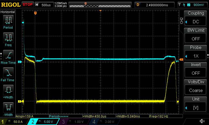
During a short circuit are set flags ASCDL and ASCD however, are not recorded safety events in life times
↧
Data Flash Setting vs Register State
Good afternoon,
My question regards the fully charged [FC] flag. Please correct me if I am mistaken, but I believe that the FC flag would be cleared when the voltage drops below 4.1 volts. Also, the FC flag would be set when reaching 4.2 volts. By the way, these values, shown in the first image, are the defaults and the application is a single cell configuration. My confusion is what state exists in between 4.1 and 4.2 volts. In the second image, the FC flag is cleared "green". How does this correlate with the data flash values in the first image if the battery is above 4.1 volts as seen in the dashboard battery icon?


Thank you for your time.
Blake
↧
bq30z55 PTC function
Hi Team,
I am writing to help on PTC question. Customers is using bq30z55 solution. Basically,they don't want to use this pin.Thus, the pin is tie to GND directly.
However, PTC PF is triggered when high discharge current testing. The fail-rate is just a few. But we still would like to look forward your advise that any way to
disable PTC PF or any way to avoid the wrong behavior?
Something we have confirmed:
1. FW is the same with golded image,
2. the trace that PTC tie to GND is very short.
↧
GPC Tool Generalization for Multiple Cells
Good morning,
I have a question regarding the GPC tool. Given the scenario that I have a large quantity of 18650 cells(all of which are the same model), would a golden GG file need to be generated for every single cell in regards to product deployment? I do realize that the learning cycle will improve the estimation accuracy of the IT algorithm. It is my understanding that the benefit of the golden GG file is for thermal optimization, and I know that not all cells will be manufactured equally, but I see this as minimal if the learning cycle is sufficient. This is why I wanted to consult an experts opinion.
Thanks
Blake
↧
↧
BQ78350-R1 Set charge value to a known value?
Hi,
Is there a way to force the state of charge value to a known value in the BQ78350-R1? We fully charge the battery before it gets installed into the unit so the state of charge at install is 100% but the CEDV system is not recognizing that the pack is fully charged.
Thanks,
↧
bq34z100-g1 write checksum error
Hello,
I am using bq34z100-g1 with firmware version 0x0016 and hardware version 0x0080.
I am using 2 cell battery so I want to disable internal voltage divider. I am following procedure given in datasheet. But whenever I write new checksum into device it is giving me error.
I donot have evm right now. Can you please help?
Thanks
Hemant
↧
Remote Battery status Monitor
Hi,
We have an application in which we need to sense the battery charge status.
Our design has two mechanical housing, electrically connected by two pins (Power and GND); we are using one fuel gauge that is connected to battery management to charge the battery controlled my local MCU
We need to check the battery charge status in the housing (2), all we have is the only two power wire that is connected between two mechanical housing.

We are looking for a solution to implement this, please let us know is there any ways to implement.
Let me know if you need any details.
Thanks !!
Regards
Antony
↧
Feul Gauge and Protections for Multiple 18650 Cells in parallel connections
I plan to use multiple Li-ion cells (18650, mostly I need 4 cells) in parallel connections for portable devices, and about to realize the following functions:
2A/4A Charging (with protections), precise percentage (1% or so) of the total electrical volume, I have chosen BQ29700(Protection),BQ24195(Charge IC), BQ27542-g1
So I have some questions:
1.Can I use one gas gauge for multiple cells in parallel connection? What should I concern, other than single cell uses?
2.Some of the 18650 cells already have protection board built in, (usually DW01+ 8205A, which is more expensive than cells only), do you suggest I use the built in ones or BQ29700? Or, do you suggest I use both if I need protections of each cells?
↧
↧
Problem in reading the BQ2060A (without EEPROM) registers with MSP430G2553 based LaunchPad
Hi,
I'm trying to read the factual and the predictive values from the internal registers of the BQ2060A which is embedded on a recently bought SAFT battery 2s1p package (app. 7.8VDC-6000mAh) without any EEPROM installed on it. The hardware connections between the BQ2060A and the MSP430G2553 (LaunchPad) are consisting of three SMBUS signals, i.e. GND, SMBUS-DATA (with 10K pull-up to VCC (3.45V) of the LaunchPad) and SMBUS-CLK (with 10K pull-up to VCC (3.45V) of the LaunchPad) ones. I have also used a few hardware setup cases, such as battery pack with a load only, battery pack without any load and any charger and finally battery pack with a load and a charger together.
In addition to the hardware setup mentioned above, I have used the below TI based software items by means of using TI's Code Composer Studio/ Version 6.2.0.00048 and the SLAVE_ADDRESS of 0x0b for the BQ2060A on the battery as well as disabling the PEC by means of commenting the related line, i.e. editing it like " //#define SMB_DEFAULT_PEC_ENABLED /*! Define to enable PEC */ ":
SMB_Master00_AllProtocols (especially for the cases "READ_WORD_TEST" and "READ_BYTE_TEST"/with 2 bytes' selection)
SMB_Master01_ReadByte_Echo (with 2 bytes' selection)
While inserting a breakpoint at the end of the test case of the code of SMB_Master00_AllProtocols (especially for the cases "READ_WORD_TEST" , I sometimes see 1, 32, 80, 592 values for the value of "ret" in the expression window while I see "., ., ., ," (various commas and dots) for the value of the "Resp_Buff" and these values are not changing in an accordance with the battery function commands, such as 0x08, 0x09, 0x14, 0x16, etc. That is, I write a command of 0x08 for reading the "Temperaure Value", but I always read "., ., ., ," (various commas and dots) for the value of the "Resp_Buff" even I change this command into the other options, such as 0x09, 0x10, 0x14, 0x16, 0x1c, etc.
On the other hand, I still see "., ., ., ," (various commas and dots) for the value of the "Resp_Buff" and these values are not changing in an accordance with the battery function commands, such as 0x08, 0x09, 0x14, 0x16, etc. while inserting a breakpoint at the end of the test case of the code with SMB_Master01_ReadByte_Echo (with 2 bytes'selection).
I'd be very glad if you let me know what to do from now on.
Thanks in advance for your very valuable feedback,
Kind Regards,
R.K. Arikan
P.S. I have also used 220 Ohm serial line termination resistors for SMBUS-DATA and SMBUS-CLK lines on the LaunchPad part and removed the protection diodes from each signal mentioned above in terms of minimizing the bad capacitance effects of them according to the knowledge on the pdf document of "SMBus-made-simple 5F00 v6".
↧
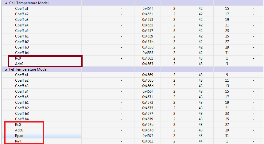
Use bq78350 family thermal Coef calculator to calculate RC0 ,ADC0 ,Rpad, and Rint
↧
BQ78350-R1 + BQ76930 , Battery Capacity (Max) (mAh) : 60000[mA] Remain Capacitor set-up ?
And using BQ78350-R1 + BQ76930.
I am a 60 [A] want to change the Design Capacitor mAh to 60000 mAh.
In TI, that can be used to change the settings 320000mA was Ido design capacity
Unchanged.
Do BQ78350-R1 has a maximum depth of up to 32A?
I want at least 32 [A]. Please let me know the solutions will favor Dream.
Thank you.
↧
bq78350-R1 and bq76930 Shutdown
Hello,
I use a design with bq76930 and bq78350-R1.When I sent ManufacturerAccess() MAC Shutdown via SMBus to bq78350-R1, the device shuts down.
But what will happend to the bq76930? Will the device shuts down too?
Thanks in advance.
BR, Patrick
↧
↧
bq34z653 and bq34z651 support in Battery Management Studio
I'm working on a design based on the bq34z653. I couldn't get an EVM for that device, so I'm doing some early work with the bq34z361 EVM. Can I get support for these devices within Battery Management Studio?
If not, I have the bq Eval Software for the bq34z651, but can not locate it for the 653. Can you provide it for the 653?
Regards,
Mike
↧
Gas Gauge + Step Down converter
Hello
We have a pcb with small size. We need to be able to go from 9V to 3.3V while being able to gauge battery voltahe for low power detection.
Is there any chip capable to ensure both function in once ?
↧
BQ40z50-R1 Calibrate with 50% current
We have calibrated our packs so that under any given load, the BQ shows 50% of the actual current. This is because our application can pull more than 32A and we had to scale the current readings. Everything else is obviously adjusted accordingly.
I looked at the pdf on 'High Capacity Packs' and noticed that this effect was achieved using a 4A load while telling the BQ it's only 2A. For our learning cycle, we used a 2A load and told the BQ it was 1A. Would there be any difference between the 2 methods (especially in the accuracy)?
Thanks
↧


