Dear Ti,
i want to connect 4 load cell with one A/D Converter, can you please suggest any ic for connect 4 load cells and get average value through i2c.
load cell detail: kg- 80, 4- wire (red, black green, white)
thank you
Dear Ti,
i want to connect 4 load cell with one A/D Converter, can you please suggest any ic for connect 4 load cells and get average value through i2c.
load cell detail: kg- 80, 4- wire (red, black green, white)
thank you
Part Number:UCC28634
We are designing a high voltage DC-DC flyback converter using the UCC28634 controller. The circuit is currently operational (starts up and somewhat regulates), but is not functioning properly due to excessive ringing on the AUX winding of the transformer during the main switch 'on' phase. This ringing is corrupting the Vsense signal and disrupting the supply regulation. I have attached waveforms of the main switch drain (red trace) and AUX winding (blue trace). Any insight into what may be causing this would be greatly appreciated.

Part Number:TPS61200
Hi,
is there any way to increase current limit of TPS61200?. Since the supercapacitors can give more current below 1 volt, it will be very usefull if current limit more than 1.3 A such as 2-3 A.
P.S. the supercapacitors application will increase in near future, and there will be need Low Input Voltage Boost Converter with large current.
If Texas instruments designs a new chips, it will be very helpful for the power community.
Thanks for support.
Akif Yigit
Part Number: LM5021-2
Hi,
I have developed flyback SMPS of rating 12V, 0.5V using switching IC LM5021-2. But output voltage is not coming.
In flyback, Can we use output voltage as bias supply to LM5021 instead of saperate bias winding?
kindly help to resolve this issue
regards,
Gajanan(Please visit the site to view this file)
Part Number:UCC2802-Q1
Hi Team,
We are penetrating our ucc2802-q1 at my customer side, we got question from customer that what is the absolute maximum voltage on OUT pin(Pin 6 as below):

As we can't find it in datasheet, but it's important for customer for refer, would you pls help provide this specific, thanks a lot!
Best regards,
Sulyn
Part Number:TPS73HD3
Hi Sir,
Could you help to check the recommended Layout of TPS73HD301 ?
when test in high temp environment, TPS73HD301 is hot. So If I layout the "NC" pin to GND, will it be available?
there have no recommended Layout section in datasheet.
Thanks and wait for your support.
Part Number:UCD9248
In the attached schematic, VIND is 12V input power supply. VDD_UCD is expected to be 3.3V. But it is not. It is around 1.5V measured at the PCB board. Could you please find the reason and tell me? Thank you so much.(Please visit the site to view this file)
Part Number:BQ24171
Hi all,
Do we have Candence schematic of BQ24171 EVM board? I only found gerber file of it? Below is the link. Thanks
http://www.ti.com/tool/bq24171evm-706-15v?keyMatch=BQ24171EVM-706-15V&tisearch=Search-EN-Everything
Part Number:TPS54331
Dear TI EE
The circuit using TPS54331DR as 5V Buck to 1.2V function,as bellow picture.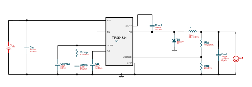
The 1.2V Vout has about 40KHZ ripple,the waveform as bellow picture

The TPS54331DR Comp Pin6 to GND Voltage waveform as bellow picture

Please help me to solve the problem.I am anxiously awaiting your solution.Thank you very much.
Best Regards
Cheney_Sun
Part Number:TPS54331
Dear TI EE:
The circuit using TPS54331DR as 12V Buck to 5V function as bellow picture
The 5V Vout has about 40KHZ ripple as bellow waveform picture

The TPS54331DR Comp Pin6 to GND Voltage as bellow picture

Please help to solve the proble,I am anxiously awaiting a solution.
Thank you!
Best Regards
Cheney_Sun
Part Number:BQ2970
Hi,
I implemented the following circuit. I noticed that DOUT is not high so the battery is cut-off. I tried with fresh battery and with a power supply, same behavior. I'm not concerned with the current or voltage protection features at this point, I just need the circuit to turn on, but it doesn't. I assembled 2 boards and both aren't working. I feel like I must be doing something wrong but I'm not sure what. Your help would really be appreciated.

thank you very much,
Martin L.
Part Number:LMR14030-Q1
Dear team,
When the customer touches the voltage divider resistors of the FB pin using their hands, there will be no output. Could you please help tell me the reason and solve this problem?
Thanks & Best Regards,
Sherry
Part Number:UCD9248
Could you please explain the following questions? Thank you so much.
1) What is the meaning of store RAM to Flash? Does it mean store the UCD9248’s RAM content into its Flash?
2) What is the meaning of Vout Max? I have set over warn, over fault. Does theVout Max make the power system impossible to produce an output voltage higher than VoutMax?

3) What is the meaning of Write Entire Design->Hardware. Does it mean downloading the design to UCD9248’s RAM and not to Flash? Will the new design run immediately after downloading?

Part Number:BQ30Z554-R1
HI All:
I want to modify some block as show below,do I use write 2 word command to modify it ?
bq30z55-R1 Technical Reference said that sbs cmd of operation status is 0x54,so input 54 to sbscmd ,but word1 and word2 ,how to input?
Thanks for ur reply.

Part Number:UCD9248
Could you please help me on this question? Thank you so much.
I have designed a UCD9248 firmware in offline mode, a portion of the design is as follows. Then I save the design to a file named Kintex-7.tifsp.(Please visit the site to view this file)

I connect the hardware and open the fusion software in online mode. I choose to download the previously saved Kintex-7.tifsp.

The software shows download error when downloading.

I connect the hardware and open the fusion software in online mode. The fusion software reads the UCD9248 displays the parameter in its flash. It shows some of parameters are correctly written to the flash. 
But many parameters are not written shown in the following figure. It is because the downloading fails when some parameters are written and others are not.

Part Number:BQ25713EVM-017
Hello,
We are looking to use the BQ25713EVM-017 as a reference design and embed it onto our production board, but have some questions:
1. Should we power the rest of our system from the VSYS/PGND port? If so, what would this look like?
Part Number:TLC5954
1.TLC5954 chip page 27 "command" configuration is not very understanding
2. TLC5954 chip page 31 "data" write, please help to confirm the correctness of my code
3. There are two places in my code writing, both in the LED.C function:
The LED_DRV_TransmitByteProcess_Com() function is the function that writes the command.
The LED_DRV_TransmitByteProcess_Data() function is the function that writes the data
At the beginning of the program, the main function enters. First, the LED_DRV_TransmitByteProcess_Com function is configured.
The LED_DRV_TransmitByteProcess_Data function control is then performed.
As a result, no LED lights can be turned on
The code are attached
(Please visit the site to view this file)
