Quantcast
Channel: Power management forum - Recent Threads
Viewing all 35901 articles
Browse latest View live

BQ40Z50-R2: Questions Regarding bq40z50 MAX Error Report

$
0
0

Part Number: BQ40Z50-R2

Hi,

I have a project which is using BQ40Z50RSMR-R2, I got below questions from my customer, I copied it below, could you please help to answer the questions:1)why the "Max error " changes from 1% to 2% after some rest without any operations? 2)how does bq report Max error as 1% or 2%? 3)is it normal "Max error" changes from 1% to 2% after rest without any operations?  4) if it is not normal, how to repair?

1.    “Max error” of the BMS is not stable. Sometimes it shows 1%, sometimes it shows 2%. Last week when we tested 520-530pcs ok, their “Max error” showed 1% at the beginning, after several days rest without any operations, it becomes 2%.  We checked with the BMS manufacturer about the parameter “Max error”, the BMS manufacturer did not give a clear reply. We need to know “Max error” can be 2%, or it should be 1%? We checked the TI’s working principle, in theory, 1% is the impedance tracking state, and 2% is the capacity learning successfully. Both values are acceptable. But the question is, why the “Max error” changes from 1% to 2% after some rest without any operations? Does it mean the BMS is not stable? In fact, we wish to get a clear reply from the BMS manufacturer. If this is normal, we will seal the batteries to arrange the shipment. If it’s not normal, please tell us how to repair?

Thanks,

Joy


LM5050-2: Usage with Diode ORing

$
0
0

Part Number: LM5050-2

Hi,

If LM5050-2 is connected with diode ORing as following picture, are there any precautions?

Best Regards,

Kuramochi

BQ25606: deep-discharged battery

$
0
0

Part Number: BQ25606

deep-discharged battery
We have a current request regarding a 18650 Li-Ion battery.
The customer is afraid that deeply discharged LI batteries will be damaged by the BQ25606 battery charger. So that in worst case the batteries will start to burn.
Our reverse polarity protection circuit has a certain quiescent current (< 10uA), which deep discharges the cell over a long period of time.
So will the charge controller always try to charge the battery, or will it stop charging at a certain voltage?
Also:
>> Is there any possible to adjust the switch-off threshold of the Battery charger?
>>Is there a way to move the switching Point of Q4?

ADP125ACPZ-R7, ADP2300AUJZ-R7 P2P Replacement

$
0
0

I need ADP125ACPZ-R7, ADP2300AUJZ-R7 P2P replacement chip recommendation, thank you!

BQ25606: Li-ion charger BQ25606 with FT232R USB to serial converter

$
0
0

Part Number: BQ25606

Hello,

I would like to make a Li-ion battery charger based on BQ25606RGET single cell battery charger. Most of the time, a comercial USB (phone) charger will be used (charge current up to 2.5A), but sometimes will this charger be also connected to a PC (max. current 500 mA) and because on my design will be also a microcontroller used, I am going to implement also a FT232R (USB to serial UART). I'm wondering that pull-up resistors (1k5) included on D+ and D- pins on FT232R will "confuse" a BQ25606RGET charger in charger detection mode, because this resistors will change a voltage on D+ and D- lines. What do you think?

Many thanks,
BR,
Dejan.

Any power module recommendation

$
0
0

Dear Sir/Madam,

I can find a perfect match for the two requirement below. Will you be able to suggest any TI power module or DC2DC regulator for this requirement? 

Best regards,

KPK

BQ27542-G1: How to use relays with BQ27542-G1 to perform an automated learning cycle

$
0
0

Part Number: BQ27542-G1

Greetings, 

I am using BQ27542-G1 gauge, with EV2400 board and bqStudio software. I would like to generate a Golden Image and thus would like to perform a learning cycle. 
I understood that the automated mode is more reliable but required the use of relays and a certain hardware set-up. 

Are there some specifications on what type of relays to use ? Is there an available electric schematic of the whole hardware set-up ? 

UC2526: I am not getting proper Control PWM Signal when output voltage feedback is connected to th UC2526

$
0
0

Part Number: UC2526

Dear SIr,

I am not getting proper Control PWM Signal in this arrangement.it is controling output volatge of Buck Converter. But getting good output volatge regulation.I have Shorted Shutdown and reset pin through a resistor. i am controling shutdown pin using transistor and Comparator.i am getting distorted PWM.i have shorted second and third pin of UC2526ADW.


ADP125ACPZ-R7, P2P Replacement

$
0
0

Hello Jeffery,
The ADP125A is an LDO, and the ADP2300 is a non synchronous buck converter.
These are supported by different TI teams, so I will split this thread after this reply and route to the 2 teams.

BQ2004: Delta T/ Delta t termination condition

$
0
0

Part Number: BQ2004

Hello,

I have two questions about the termination condition of the BQ2004, we are using it with a 4x AA VH 1900 cell battery pack.

  • Is it possible to use the  Delta T/ Delta t  and the maximum voltage termination conditions at the same time ?
  • How to implement the  Delta T/ Delta t termination condition, taking account that the battery pack NTC resistance value change inconstantly with the temperature.

The NTC reference is 103AT-2, from Semitec.

Thanks,

Kevin

TPS23756: Q1 (Si7119DN) was burned

$
0
0

Part Number: TPS23756

Hi anyone who can help,

My POE schematic can be found in my previous post:

https://e2e.ti.com/support/power-management/f/196/p/811015/3002427#3002427

It's working, but yesterday I got a problem. The P-channel mosfet was burned in 10 mins after power on.

At beginning, I connect my POE with my load(about 1.5A~2A, 5V), and use the thermal camera to monitor the heat spots. Everything is normal; Q2 (Si7852DP) was about 55~60 C degree, Q4 (Si7456DP) was about 45~50 C degree. No other high temperature spot found.

But after 10 mins running, the Q1 (Si7119DN) suddenly smoked and burned. This chip was not one of the heat spots. The C2 (0.047uF, 250V, 1206) was not broken with the testing by multi-meter.

Could please tell what's the potential reason to cause it? If (just if) the Q1's gate pin shorted with the source pin, will that cause the problem?

Sincerely,

Kevin

TPS54240: TPS54240 EN pin off output problem

$
0
0

Part Number: TPS54240

Hi Team,

When I use the TPS54240, after the EN pin is grounded, there will still be a 1.8V output.

Please check schematic attached. thanks.

Is this normal? Why?

Sincerely

Kevin(Please visit the site to view this file)

UC1825A-SP: UC1825A-SP Under Voltage Lock Out threshold overtemrpature

$
0
0

Part Number: UC1825A-SP

Hello,

Question about the UVLO threshold for the UC1825A-SP. The spec is about 9.2V nominal. What is the coefficient of this threshold over temperature ? Is it increase or decrease with Hot temperature ?

Best Regards,

Jason Nguyen

TPS23861: PSE detection problem

$
0
0

Part Number: TPS23861

Hello,

We use a TI PSE chip to make a surge protection with a Schottky diode between power supply and GND, as shown below.
     It has now been found that the leakage current of this diode affects the detection of PD by the PSE.Only some boards have problems,not all.Demand assistance:
1. How much current does this diode leak affect the normal detection and identification of PD?
2. We have mass produced boards.Is there any way to screen out the diode with large leakage current?

PTH12040W: PTH12040WAD, PTH08T210WAD, PTH08T240WAD, PTH08T220WAD - What is the tolerance on the pin length?

$
0
0

Part Number: PTH12040W

These are through hole devices. Your datasheets list the length as 0.14 (3,55). Could you tell me what the tolerance is?


UCC28C42: Pulse skipping in voltage mode control

$
0
0

Part Number: UCC28C42

Hi,

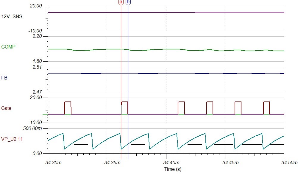
I'm designing a 40-200 VDC to 12 VDC @ 0.1 A buck converter using the UCC28C42 in voltage mode control. Towards the upper limit of the input DC voltage, the controller starts skipping pulses. I was able to replicate this behavior on TINA, but I don't understand why the controller skips pulses.

The 5th curve on the attached picture shows the CS ramp(teal) and the COMP(black) after the 2 diode drops & voltage divider (internal node probed in the unencrypted spice model provided by TI) which are inputs to the PWM comparator. It can be seen that the COMP is well within the CS ramp voltage range, but during certain periods there are no pulses from the controller.

I was hoping that someone could help me understand this behavior. The design is confidential, but I'll be glad to email the TINA files if required. 

TPS54318: TPS54318 loop compensation - Datasheet formula vs TINA vs Webench

$
0
0

Part Number: TPS54318

Hello Team,

we are currently checking a project to step down the voltage from 5V down to 1V @ 1A.

We are using the datasheet, TINA and Webench, and we are getting different results.

Some are quite different, thus the questions:

  • What is the most reliable, theoretical way to determine the components for the loop compensation? (datasheet, TINA, Webench)
  • How much is expected to deviate the result computed out of the datasheet formula from TINA and Webench simulations?
  • Which model is more reliable for verification - the step response in the transient model, or the average model?
  • Is it Webench using the same spice model as the one given for TINA?

Thanks,

SunSet

UCC28950: UCC28950 voltage mode control loop

$
0
0

Part Number: UCC28950

Hi Support team 

I would like to use voltage mode control loop, however, the purpose is to reduce the CT and the CS PIN connection to the UCC28950.

if don't used current control loop, can we remove the CT and pull down the CS pin?

LM5116: Turning on, getting to target output voltage and immediately turning down to 3.5-4V

$
0
0

Part Number: LM5116

I am using the LM5116 to buck from 24-100V in to 18V out. I have had this working but something appears to have broken and I cannot figure it out. The converter turns on properly (it appears) and then the output voltage starts dropping until it reaches about 4V. Right not the output power is isolated from the rest of the board, so there is nothing pulling down the output. I have also applied an external 18V to the output to ensure there is no shorts or anything.

(Please visit the site to view this file)

Yellow is the enable signal, and green is the output voltage.

(Please visit the site to view this file)

Here, yellow is the enable, blue is the soft start, green is the COMP pin, and purple is the CRAMP pin.

Looking forward to some assistance :)

Thanks!

TINA/Spice/TPS25982: TPS25982 PSpice abilities

$
0
0

Part Number: TPS25982

Tool/software: TINA-TI or Spice Models

Hi Team,

With respect to the TPS25982 to confirm, does the PSpice model for the active current limiter versions include any type of TSD behavior, based on generalized performance for the limit, and how long/much the source current exceeds the limit?

Viewing all 35901 articles
Browse latest View live


<script src="https://jsc.adskeeper.com/r/s/rssing.com.1596347.js" async> </script>