Part Number: TPS61196
Hi Team,
May I ask how I can choose VIFBV?
The display has four strings of LEDs, and the current is 102mA (DUTY 100%).
When R11 = 49.9K is selected, how to choose R10?
Part Number: TPS61196
Hi Team,
May I ask how I can choose VIFBV?
The display has four strings of LEDs, and the current is 102mA (DUTY 100%).
When R11 = 49.9K is selected, how to choose R10?
Part Number: BQ78350-R1
Greetings,
We are using bq78350-R1 and the GUI is bq studio from TEXAS. I have a doubt regarding this RSOC. If SOH is 100% and battery voltage is full the why the RSOC is 50%
I hope u will revert soon.
Thanks and Regards,
Parimala
Part Number: TPS61240
Hi all, thanks for coming to make my life easier.
I am using the chip to power a set of OpAmp which should need around 50-60mA. For debugging purpose I am using a power supply to power up the TPS61240. So here is the hypothetical setting of the debugging circuit
Chips: TPS61240
Input cap: 2.2uF
Inductor: 1uH
Output cap: 4.7uF
Input voltage: 3.6V
Output voltage: 5V
Things were somehow ok when no loading is applied. Which the power supply suggest the current supplying is less than 1mA. However when the loading was applied, the output voltage dropped significantly. A chip is connected as a test to verify the drop. Which the output voltage drop from 5V to 3.7V, while 13mA was being drawn from the supply. Meanwhile the chip is making the buzzing sounds to tease me and mess with me.
Assumed that maybe the cap values isn't correct since I am getting them somewhere in china, I do tried to change the setting of the circuit and the output characteristic do change a bit. But I am still clueless since I do follow the data sheet for the prototyping. So any good dude here got any idea?
Thanks again for coming.
Part Number: TPS62125
Hello,
I have TPS62125 sourced with a 16.5V battery. Its Vout is set to 3.3V to power an MSP430 MCU.
MSP430 is used, among others, to monitor low battery, e.g. when battery voltage <14.5V, through PG pin.
- Is this possible? (i.e. PG becomes low when input voltage < V_threshold, while TPS62125 still powers MSP430)
- Is there a simple circuit to be implemented?
Many thanks.
Best regards,
Mauro
Part Number: TPS57160-Q1
Hello,
I wanted to know, if output pin shorted to battery voltage ( min 6V and max 60V) and Ground? any inbuilt protection available or externally, we have to take?
Thank you,
Regards,
Srinivasu
Part Number: TPS54160
I am trying to simulate the transient reference design downloaded directly from the tina website, but it seems to complain about the operating point not being found. I have read and followed what was suggested in other posts, and have also tried to implement the instructions given below the downloaded reference model, but none of it seems to work. I also noticed that I can only get some output when the input itself is below 2 V.
Does anybody have any suggestions?
Part Number: BQ24171
Hi,
We are designing a circuit that include a lithium battery charge (BQ24171RGYT and BQ27441DRZR-G1A).
The circuit for the charger is very similar to the one shown in BQ24171EVM-706-15V (for 1 cell). It includes the “Battery discharge MOSFET gate driver output” BATDRV mosfet.
The circuit needs to provide the option to disconnect the battery during storage.
One option is using a bidirectional mosfet circuit next the battery connector (it will be triggered externally by a tiny TACT switch, active low).
Question:
Can we use the BATDRV mosfet to disconnect the battery from the load? Using an AND circuit (inputs # BATDRV and TACT switch associated to a latching circuit).
Or can you advice other way to do it? No much pcb real state is available.
Thank you in advance
Part Number: TPS56339
Hello,
I used TPS56339 for one of my design for 24VDC to 5VDC conversion, upon testing it for 4 hours @ 1A load, I shorted the 5VDC terminals to test for the over current and TPS56339 caught fire.
Please let me know whether it is design problem or is it the issue with TPS56339 itself
I here with attaching the schematic file.
Regards,
Prasada(Please visit the site to view this file)
Part Number: BQ76PL536
Tool/software: Code Composer Studio
Hi all!
I designed a pcb project with BQ76PL536 .And now , its time to code! But I have a problem. I want to find the example code project for MS430 . Can anyone share with me a link? I searched a lot but I couldnt find. How can I find it ? Please send me a link.
Part Number: LM5166
Hi,
Would you response below my question ?
[Back Ground]
Currently, I am designing 3.3V non-isolated regulator with LM5166YDRCR(COT mode).
Then, I have simulated with LT spice to confrim swicthing behavior.(Spice Model "LM5166_TRANS.lib " that is provided TI web site was used.)
But , Observed switching frequency(SW pin) is 114.7KHz in spicte of Rt = 39.4kohm(According to foumula (4) in datasheet, It should be 478kHz ).
[Schematic]
Please see attached file.
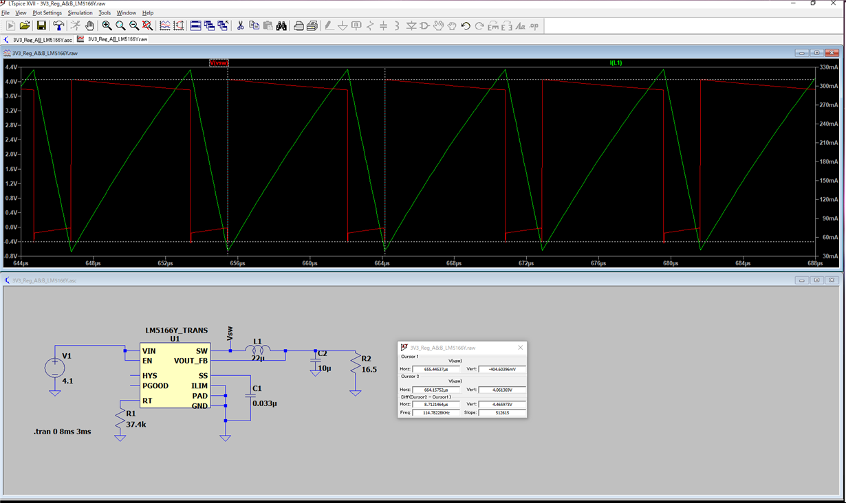
[Question]
1) Why is swicthing frequecy 114.7 kHz, not 478 kHz ?
2) Would you provide foumula to calculate swicthing frequency under this condition ?
It is urgently item for me. So, Would you please provide response as soon as possible ?
Part Number: UCC21225A
Hi Team,
Here is a question from customer.
When there is PWM on INA/INB, OUTA and OUTB keep high and no change.
In customer's application,
pin4 is connected to 3.3V, pin7 is floating. Is it OK? pin4 and pin7 are connected internally, so it seems OK.
DISABLE is connected to GND, DT is floating, is it OK? From datasheet, it seems OK.
VDDA is 120V, VSSA is 110V, VDDB is 12V, VSSB is GND.
Please kindly add your comments on possible reasons. Thanks.
BRs
Given
Part Number: LM5141
We have used the LM5141 to design a switching regulator which converts an input voltage between 24V and 60V to an output voltage of 5V. We're running some test measurements using a load of 2ohms. When measuring we noticed a ripple of +/- 168mV. I've added the scope images here below. Note however that we used the scope in AC coupled mode so we only see the ripple the same is seen if we did it in DC-coupled mode.
We personally think it's a grounding issue. We have however followed (to our knowledge) all lay-out advises from the datasheet. The circuit as seen below was also created using the WEBENCH tool with the only difference that we picked other MOSFETs which can dissipate more heat. The WEBENCH tool estimated a ripple of 2mV We've tried to increase the output capacitance however this does not fix the issue. Another thing which increases our belief in a grounding issue is the fact that the same ripple is seen on the 3V3 line which is generated from the 5V line though an LDO. Would there be any suggestions to why or how this issue happens/can be solved?


Part Number: LM5085
hi,
I've a problem, I need a supply with programmable current limit. I've chosen for the LM5085 because it has that function built in. The problem though is that the current limit doesn't work in my design and I have no idea why. I have read the whole data sheet multiple times, but I don't have a clue why this doesn't work.

Part Number: LM2587
Hi there, I want to use this chip for two different purposes. 1) to boost a 15V to a 24V and provide atlast 3A of current and another to 2) regulator 15V at 4A or more amps. I am confused on how to go about picking these passive pieces. can someone point me in the direction for how to go about doing this?
Part Number: UCC28061
Hi,
I used UCC28061 @ 1.5kW. It works well but I saw on grid current some peaks around 0vac. If I increase the power, the current increase too and the peak is less visible but in transient it is a trouble.
How can I smooth the current and obtain a perfect sinus ?
Regards
Ol
(Please visit the site to view this file)
Hi team,

Best Regards
Wesley Huang
Part Number: TPS737
Hello,
I believe the TPS73733 is the 3.3-V fixed voltage version of the LDO. The datasheet says "Fixed voltage versions only—connecting an external capacitor to this pin bypasses noise generated by the internal bandgap, reducing output noise to very low levels." for the Pin Function of NR/FB.
Thanks,
Vibhu
Part Number: LM3150
Tool/software: WEBENCH® Design Tools
I have a 24V input converting to 16.8V output with a 6A load. I built the design in Webench but the simulation shows a consistent output voltage of 1-1.5V higher than 16.8V. I have a prototype system built as well that shows the same results . The calculations from the datasheet run manually show similar values to Webench as well. Is there something I am missing that would make the output voltage that much higher than indicated?
Part Number: UCC28880
Hi,
I am using these two chips in an isolated Flyback converter (Vin = 300V, Vo=700V) and with the same transformer (Lpri = 5mH; n=1:2) I get different results.
When I use UCC28881 everything is perfect and I can charge the output capacitor at 700V fast enough as needed by the application.
However, when I change the IC to UCC28880 (which has a lower current limit) the primary current is somehow disabled and I see only an spike for about 200ns (it is not the lower current limit of this chip or the transformer saturation).
Now, when I change the input voltage to 200V, I clearly see a ramp-shaped input current but with higher oscillation as compared with UCC28881.The oscillation frequency is around 500KHz.
Cin = 100nF
L_primary = 5mH
Can one of you experts please help me to find out the reason for these oscillations and resolve the issue?

V_IN = 300V, CH4: Primary current of Flyback transformer, CH2: Drain-source voltage

V_IN = 200V, CH4: Primary current of Flyback transformer, CH2: Drain-source voltage
Please note the oscillation (around 500KHz) at the very start of the primary current ramp which is not damping fast either.
Part Number: TPS61032
Hi,
I recently posted question forum about behavior of following schematic, I changed PCB footprint, but issue persisted (low voltage on output and high consumption on empty load).
Input voltage was 2.4V, output voltage was 1.2V. Consumption was around 220mA. When I raised input voltage to 2.8V, consumption came to 460mA a I noticed, that capacitor C3 is getting overheated.
I assumed that somehow C3 is causing short, do I de-solder it from PCB. After testing again with input voltage 2.4V I got 5V on output (as expected) with negligible consumption. When I hookup Arduino board as
load, consumption went to 50mA, as expected for such board. After testing output on oscilloscope I noticed, that obviously there filtration is missing (voltage oscillate 10%). When I calculated C3 I got
value 160uF and supply tantalum capacitor 220uF, 6.3V, tolerance +/- 20%, ESR 35mOhm. I assume, I need, but am I right regarding parameters? Thank you for your help

