hey all
after finishing the learning cycle,i realised that the learning cycle is 36 instead of 0!
what should i do ?
thank you
hey all
after finishing the learning cycle,i realised that the learning cycle is 36 instead of 0!
what should i do ?
thank you
Part Number:BQ78350-R1
Hi,
Let's say for instance I calibrate a battery (temperature, voltage, current, current offset), change all the settings and protections for the battery to the way I want it, acquire and load the data for the CEDV config and Chem ID and basically create the "perfect" battery... fully functional, just the way I want it. Then let's say I wanted to make a second battery just like it and decided to install the .srec of the first on to the second battery.
Question:
Besides non-essential settings like serial number, what would is everything that I need to do to this second battery for it to function as perfectly as the first?
Thanks,
JP
Part Number:BQ34Z100-G1
We have an embedded system that works on a battery pack consisting of 4 cells (IFR26650, 3200 mAh, 3.2V), similar to these cells.
Our custom PCB contains a BQ34Z100PWR-G1 on a shared I2C bus, that can be accessed with the STM32 CPU we are using,
or directly by connecting an external connector to the I2C bus. The system must be turned on for this to work.
Circuit connection diagram
With Q1 an IRLML6402 and Q2 an IRLML6246.
We have an EV2300 and are trying to configure and calibrate the gauge with bqStudio so we can later flash an image directly to the
gauge or have the CPU configure it with the same settings through I2C (optional).
However, it's a bit unclear how some of the registry values must be configured to do a successful calibration.
Also, it seems that bqStudio is quite unreliable, since it often reports CRC check errors on read or write, or other 'unknown errors'
when trying to calibrate. If it auto-detects the gauge in the first place... Selecting the gauge from the list claims that it's not compatible'.
I am using the most recent stable build from the website (v1.3.54.1 from July 2017).
Current register values:
| Design capacity: | 6400 mAh |
| Design energy: | 81920 mWh ? |
| Cell charge voltage: | 3.475 V |
| LED_Comm/Alert: | / |
| Number of series Cells: | 4 |
| Pack Configuration: | VOLSEL is set |
| Voltage Divider: | 17100 mV (Max BATT+) |
| CC Gain/CC Delta: | 100 Ohms? |
| Load Select: | 1 ? |
| Load Mode: | 0 ? |
| Cell Terminate Voltage: | 2.5 V |
| Quit Current: | 50 mA ? |
| Qmax Cell 0: | 1 ? |
The chemical id seems to be 0x0444, but bqStudio fails to write this to the gauge with an unknown error code when trying to update.
Nominal system draw current is about 48 mA (this is drawn when the PCB is on and the EV2300 is connected).
The draw in use ranges from 200 mA to spikes of ~2000 A.
Calibrating current always fails, saying I need to apply a discharge current of at least 1A (I don't currently have something that can provide this available).
However after entering -48 mA and clicking away the error message, the gauge on the left indicates the correct value of -48mA...
Calibrating the offsets seems to be working.
Calibrating voltage always fails saying that the value must be in the mV range, but the entered value of 10000mV is somehow not correct...
Temperature calibration (like the others) often fails, but then appears to be correctly set.
Any help would be greatly appreciated. Thanks in advance.
PS It's possible that I bricked a test gauge, since it cannot be detected anymore on the I2C bus. Is it possible to recover it somehow?
Part Number:BQ78350-R1
Hi
Our customer has one question for about Lifetime Remain data.
Customer has some error and found this Lifetime data
This remain data is over 11A with Charge condition.
a) Lifetimes Current Max Charge Current 11095 mA
We thinking this Data record when empty Battery Charge with Rush Current.
But we do not hope Record this Charge Rush Current with Lifetime.
We thinking something dose not detect by BQ78350R1 with BQ76940 as system.
[ Question ]
a) Could you tell us Rush Current Detect time at Charge condition.
This mean , Rush Current = Over Charge Current .
If we know the detection time of the device we will change HW and SW so that
inrush current will not be detected.
SCD and OCD have Delay Time settings, but Over Current Charge does not have that setting
Could you tell us about this this Over Charge Current detect and judgment time ??
and Can we change this Detect time with something resister ??
b) We want to know how to detect this Charge Rush Current by BQ78350 or BQ76940??
Yes , we know about this Current measure by SRN/SRP , this mean is just peak Current measure
or several sampling point measure , Average Current measure ... etc.
Any way, we dose not hope Data Flash remain when Rush Current as Over Current Charge Condition.
Thanks and Regard
March Jasper ( Sugimoto Japan Disty )
Part Number:BQ78350-R1
Hello,
I am using the latest BQ studio (Ver 1.3.80) to configure BQ78350-R1(gas gauge) present on the BQ79640EVM.The EVM is interfaced via EV2400.
I am trying to program the gas gauge with new configuration of cells, cell chemistry, capacities etc and save the setting to a .srec file.
All related posts on the forum refer to 'Golden image' and 'programming' tabs (plugins) that I don't see in this build of BQ studio.
I am referring to this post: https://e2e.ti.com/support/power_management/battery_management/f/180/t/489947
Setting window>preferences>global preference to 'show advanced views' does not bring up these tabs.
The same was observed with BQ studio Ver1.3.54 build.
Are the tabs supposed to appear for specific gauging ICs or am I not using the right BQ studio version?
Any pointers would be helpful.
Thank you
Part Number:BQ34Z100-G1
Hi,
I am using a BQ34z100-g1 with an 8s2p LiFePO4 batteries. I have one doubt about the Cell Termination Voltage.
¿What are the condictions that mus be met in the BQ for the SoC to go to 0%?
I have done two tests:
- Discharge the battery from 100% to this voltage (Cell Termination Voltage x 8 (number of cells)). Then the SoC falls to 0% (regardless of the SoC it had before reach this point)
- With battery at a high SoC(for example 70%) quit the battery (but not quit the BQ34z100-g1 power supply). Then the BQ shows voltage of 0mV but the SoC remains at 70%.
Is there any current consideration in addition to the Cell Voltage Termination that must be met for the SoC to go to 0%?
Best regards,
Part Number:BQ34Z100-G1
Is TI able to provide the bq34z100-G1 going to production paper? I need the code scripts to know how to program Bq34z100-g1 via MCU.
Hope you can help me with that,
Thank you.
João Crespo
Part Number:BQ27741-G1
Hi TI--
I'm new to battery fuel gauging and have been experimenting with Sparkfun's Battery Babysitter:
which is a combo of your BQ24075 battery charger and a BQ27441-G1A fuel gauge.
I am trying to use a 4400mAh LiPo battery that consists of two 2200mAh cells wired in parallel:
cdn-shop.adafruit.com/.../C449_-_ICR18650_4400mAh_3.7V_with_PCM_20140728_APPROVED_8.18.pdf
The host is an atmega328p, and I have had little issue reading values such as state of charge. Since I am still writing the host code, I am reprogramming the host a lot, but in each iteration, the reading and reporting code is not changed. Every time I reprogram and poll the fuel gauge, I get significantly different values. For instance in one programming cycle, I get 61% then in the next, 26% or some other random number. If I let the system sit for a while and charge from USB, the SOC value climbs slowly as I would expect, but again, as soon as I reflash the host (via ISP) I get some other, lower value. Perhaps I am missing something as I am new to fuel gauges, but I would think that the stats from the gauge would remain somewhat constant regardless of what the host was doing. I would appreciate any suggestions. Thank you!
--BB
--BB
Part Number:BQ30Z554-R1
Hi Guys
On the circuit BQ30Z551 PTC PIN design 10k on the ground, the PTC function has been disabled, but why PF and PTC will still light?? There are other triggers??
1.The battery has been testing Shutdown mode during the PTC. Is there an association? please find the attachment that is the operating file
2.How to Enable and DIsable PF/PTC ? Is there only one hardware method enabled? The hardware is already Disable. Is it possible to make it act by using software instructions? Is there method to make PF/PTC act by the command when the PF/PTC was enabled?
Any feedback are appreciated. Thank you

Part Number:BQ20Z95
hi,
A customer has a question about our software bq Evaluation
he wants to know how to enter the passcode to unlock the FAS,SS,
how to get the file from the device, and download the file into another device.
Part Number:BQ27426
Hi Guys,
I know the gauge looks at the rate of change of OCV when relaxing. If we are doing accuracy testing (not learning cycle), what do you recommend as a relaxation time after charge and discharge? Is there a register bit to look at to determine if the relaxation time is sufficient?
Thanks,
Sal
Part Number:BQ27545-G1
We are communicating to the bq27545-G1 in an RRC battery pack. Our results from the Temperature() command are not coming back as we would expect. The data sheet says the units for this data are in 0.1K in Table 11 but the description paragraph says deg C. How is this data stored and read back when the command is called. We are expecting temperatures from about 25 - 60 deg C based on another external thermistor read out but are only getting values from about 27-35 deg C from the bq27545-G1.
Any ideas?
Thank you,
Ethan
Part Number:BQ28Z610EVM-532
I have some problems using the BQ28Z610 in my battery pack : I use two packs in series (two identical packs with a BQ28Z610 in each). When the first pack opens due to discharge, the other pack continues to supply current through the application, so I think there is a current pack in the pack, even when the MOS are open.
On the EVM, a diode D1 is use in series with PACK pin of BQ28Z610. I can(t found any explanition on it. Why it should be added? As I have not this diode on my design, it could be the reaseon of my problem (current flowing through PACK pin)
Best regards,
Part Number:BQ28Z610
I am not to get the Over Current Discharge or Charge charge values to cause the FETs to actually turn off.
For a test: in BQStudio I am setting the value on the Protections page to OCD threshold to -400 mA but it will not shutdown even if I set the load resistor for 2 amps out of of the pack terminal.
Do I need to enable OCD somehow? Any idea what I am missing? gg export attached.
In the battery status register, the bit for init is 1 (shown in the upper left orange highlight. The data sheet says that 1 here means initialization is "active". Should init go to 0 when initialization is complete, so is it not completing the problem?
Toggling the FET EN does turn the pack voltage on and off as expected.
Also the current register show positive current being used at the correct magnitude but I was expecting charge to be positive and discharge to me negative.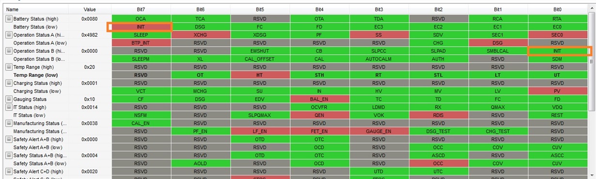
Part Number:BQ78350-R1
Hello TI Team,
We're using the BQ78350-R1 Li-Ion Gas Gauge / Battery Management Controller with BQ7692000 AFE in our latest product. For a battery pack we are using a 14.4V 200mAh 4S http://www.batteryspace.com/custom-li-ion-18650-battery-14-4v-2-6ah-37-44wh-4-2a-rate-4s-s-icr18650b4-rechargeable-battery.aspx.
Our design uses two BQ78350 gauge/AFE/battery packs in parallel. One gauge is at 0x16/17 and the other is at 0x12/13. Is there a way to switch between the two in BQstudio? I can set command via the Advanced comm SMB tool, but I cannot switch to the
When I shutdown the gauge at 0x17 I am able to connect to the gauge at 0x12.
Upon rebooting the gauge it reports about half of the capacity (44%).
The battery is fully charged showing 16380mV before and after the shutdown and reboot.
Should the gauge report 100% since the voltage is at the max.
Does the gauge have a way to better estimate the full charge?
How do you get the gauge to report 100% capacity after a reboot?
When I complete a qualified discharge the learned capacity is reduced by the FCC learn down amount. My design capacity is 2600mAh but the learned capacity is now at 1015 after a few qualified discharges.
On the other second gauge it reports 2100 mAh learned FCC. I cannot get a consistent behavior between the two gauges for FCC.
The total voltage, cell voltage, and current measurements appear to be calibrated and accurate in BQStudio.
Does this mean that the battery capacity is truly lower than the specs design capacity?
What other factors play into the configuration of the capacity?
I have attached an export of the data memory for the BQ78350:
If I am using a battery cell that is already characterized do I need to go through the activity of generating the CEDV coefficients?
I have selected the Chem ID: 0x0230 (LG 18650 B4 2600mAh)
I have not yet gone through the temperature profile logging/gauge parameter calculator to get the CEDV coefficients. I have not done this yet because I was assuming that the coefficients are only necessary to increase the accuracy of the gauge but not absolutely necessary to get the gauge working.
We have the battery pack thermistor connected to the charging IC (LTC4162) for a primary purpose of safety and we have a fixed resistor at the TS1 pin that reports 35 degC.
Do we need to have the pack thermistor connected to the gauge for the CEDV gauging to work properly? How much error is produced if the thermistor is not present?
Part Number:BQ27542-G1
Hi,
Where can get BQ27542-G1 original device firmware? Tools & software web page can't get it.
Part Number:EV2300
All:
I want to develop a software to test our battery by TI EV2300,only read and write some commands,using Microsoft Visual Studio 2015 c#. but I don't know how to do it in c#,I used the vb6 before.I need help,I hope that Who can give me some c# sample sourcecode.Thanks very much!
Part Number:BQ35100
Hello everyone,
I have a small microcontroller project with a single non-rechargeable (CR2430, 3V, Lithium Manganese Dioxide, 300 mAh) cell, followed by a boost converter for 3.3V output.
Don't know if it's relevant, so.. in sleep mode it draws some <0.1mA, while active mode consumption is >30mA.
I'm looking to add a battery gauge to my project, so that device could send current battery % value to operator, so that he can decide if it's time to replace the cell.
In TI battery management range I've only found BQ35100, that seems to suit my needs. But it's a rather large chip with 15 external components (in example circuit). Are there any alternatives I may have missed?
Is it possible to use BQ35100 to measure current consumption of my board in different modes of operation during debug?
Thank you!
Part Number:BQ40Z60
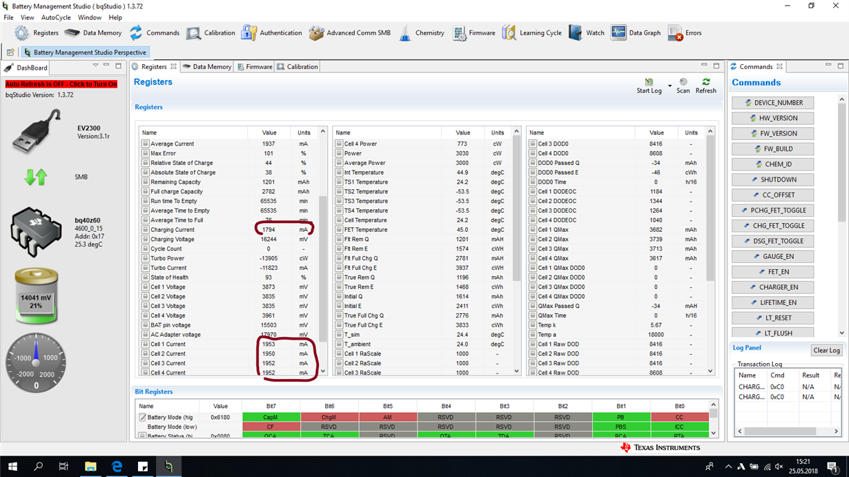
I have custom charger design, based on BQ40Z60 evaluation board, with changes:
- without all U1 protection circuit
- without precharge circuit: F1, Q7, C10, R18, R22
- AFEFUSE pin tied to GND
- R14 changed to 1K (we have high voltage drop on ACP pin after charge was enabled)
- C18, C20, C24, C25, C27 changed to 4,7uF/25V
- no Q10-Q13 led circuit
- voltage divider: R21 = 330k, sum of R26-R29 = 24k
- BQ40Z60 firmware: bq40z60_v0_15_build_21
- connected cells: 4x parallel NCR18650GA-Panasonic with thermistor and cables for balancer
We have problem witch charging currents mismatch. BQ studio is reporting charging current to 1794mA, but for cell1-4 show about 1940mA. But to the cells is going about 2300mA (we connected 0.01R to +V4 cell, and measure voltage drop).
All voltages are calibrated and reported properly.
When I want to calibrate current (using that add-on 0.01Rfor metering), CC Gain, and Capacity Gain drops to 4.324. And all reported currents got messed up.
But sometimes I have "good" board, charging current 1794mA is almost the same as cell1-4 currents, but physically it delivers to battery about 2000mA. It works on the same golden image as other boards, only voltage calibration was done before metering.
How to fix that?
(Please visit the site to view this file)
Part Number:BQ28Z610
Hi sir,
Recently, we ues the gauge bq28z610, and want to know the something about it, as follows:
1. Is Shutdown mode the same to Ship mode? (Ship mode for Battery shipping!)
2. If we want to set mode from Normal to shutdown mode, how to set the register and configure it?
3. How to wake up the Battery from shutdown mode to Normal mode? for example: configure the register or others way.
BR,
Jingle