Quantcast
Channel: Power management forum - Recent Threads
Viewing all 35901 articles
Browse latest View live

BQ25713EVM-017: About Load Register in Battery Management studio

$
0
0

Part Number:BQ25713EVM-017

Hi,

Could you tell me about Battery Management studio GUI for bq25713.
I set bq25713 register using Battery Management studio and made the data into a text file.
However, I loading text data was not reflected.
As an example, I will attach a screen shot of setting the charge current resister.

(Please visit the site to view this file)

Please tell me the reason and solution.
If this problem is not resolved,
I have to enter the setting every time.

Could you give me your support.

Best Regards,
Yusuke


TLV62084: Efficiency at 5V input voltage

$
0
0

Part Number:TLV62084

Hi, team,

Could you please share the efficiency information 5V input voltage, 3.3V out voltage in TLV62084?

Regards,
Nagata.

LP87524J-Q1: Default voltage of Buck3 regulator on LP87524J

$
0
0

Part Number:LP87524J-Q1

Hellow

I want to know the default voltage of Buck3 regulator on LP87524J.

In the data sheet(Rev. B), "BUCK3_VSET[7:0]" is described as "0xCA for LP87524B, LP87524J, 0xB1 for LP87524P".
I understood that the default  voltage of Buck3 regulator in LP87524J is 2.3V (0xCA) .
(Page 44 in the datasheet(Rev. B)" (*1))

In the data sheet(Rev. A), "BUCK3_VSET[7:0]" is described as "0xCA for LP87524B, 0xB1 for LP87524J".
I understood that the  default voltage of Buck3 in LP87524J regulator of is 1.8V (0xB1) .
(Page 43 in the datasheet(Rev. A)" (*2))

Which the default voltage of Buck3 is 2.3V or 1.8 V in LP87524J?


(*1) In the link "LP87524B/J/P-Q1 Four 4-MHz Buck Converters for AWR and IWR MMICs datasheet(Rev. B) )"
     SNVSAW2B –APRIL 2017–REVISED DECEMBER 2018

(*2) In the link "LP87524B/J-Q1・・・ (Rev. A  (Japanese Version))" 
     JAJSE47A –APRIL 2017–REVISED NOVEMBER 2017

Iwao

Lm25019

$
0
0

I am having a issue with the formula given in the datasheet of lm25019 like calculation of switching frequency,  inductor selection formula. Can you help me with these problems.

Regards

Sourabh

TPS63000: Application note SLVA251 output voltage calculation method

$
0
0

Part Number:TPS63000

Hi

Could you please let me know about output voltage calculation method in the application note SLVA251?

Vout = ?  (depend on R1, R2, R3, Vfb, Vdac)

Thanks

Muk

BQ24253: Heating issue on BQ24253

$
0
0

Part Number:BQ24253

Dear Sir/Madam,

We were using BQ24266 in our circuit, as it is NRND we have replaced the BQ24266 circuit using BQ24253. Attaching the schematic for the battery charger page.
The IC is heating when applied 8.2V@1A, and 8.2V@2A.
L2 Inductor part number is  SRP5030CA-1R0M

for testing we have not connected the battery. D+ and D- has not connected as it is not required for our applications. We need stand alone mode not IIC mode. Input 8.2V (+12v identifier name) is fed from LMR14030. But the actual input voltage is changed to +8.2V. Its not 12V.

Please help to identify the heating issue cause.

Regards,

Muthu S(Please visit the site to view this file)


BQ78PL116: Chemistry file for MOLICEL INR18650A

$
0
0

Part Number:BQ78PL116

Dear Sirs,

The Li-ion cell we are utilizing in our battery is obsolete. The plan ist to replace it by a model of MOLICEL, the INR18650A.
Now I'm wondering which chemistry file might be the best to pick? Maybe there is even a chem file exactly for this cell.

I would be very grateful for a short feedback!

Maybe even a fitting chem file would be perfect!

Many thanks in advance!

Markus

TPS56628: Light Load Skipping Mode with greater Ripple Voltage.

$
0
0

Part Number:TPS56628

Hello Team,

My customer is developing 12Vin to 3.3Vout_5A (OCP ≥6A) with TPS56628, however, the 3.3V ripple voltage <35mV is required (spec 45mV), but TPS56628 features light load skip mode comes greater ripple voltage 50mV at 0.15A which is over spec.

They are wondering if TI has P2P device can directly replace TPS56228 without this need to re-layout, so this will help them to ship out power board sample to their customer soon, can you help?

If no P2P device, what would you suggest most similar device with same package to instead?

Thanks a lot for help.

Martin Chien


BQ78350-R1: hardware protection current limit

$
0
0

Part Number:BQ78350-R1

Hello 

I'm having difficulties changing the "Over-current in discharge threshold setting" on the BQ78350 companion controller (used in with thew BQ76930 AFE). The hardware protection current limit is tripping at 8A, which corresponds with the 8mV (default value defined by OCD_T3 Bits 3-0 and RSNS =0) produced across my 1mOhm current sense resistor. I wish to increase the hardware protection current limit to 32A, however when I change the AFE PROTECT 2 settings in BQStudio they (PF Status menu) it does seem to change the current limit. 

I have set the OCD & OCC limits to 20A - But the hardware protection current limit is tripping at 8A. 

Can anyone advise me on the correct way to alter the hardware protection current limit?

Many thanks

Stephen 

TPS61194: Setting Vout against max LED Vf

$
0
0

Part Number:TPS61194

Hi team,

I used TPS61194 in a previous design, which used an LED string with a max Vf of 30.6V. Per the note in Section 7.3.1, I set my Vout to 1.3 * 30.6V = 39.78V. [Related section: "VOUT_MAX voltage should be chosen based on the maximum voltage required for LED strings. Recommended maximum voltage is about 30% higher than maximum LED string voltage."]

In an upcoming design, the LED string I'm using has a max Vf of 37.4V. Taking the same approach, I should have a Vout of 48.62V, which is too high for the device.

So I have two questions:

  • Am I approaching setting my Vout correctly against my Vf?
  • Given my new Vf, am I correct in assuming I need to find a new device for this project?

Thanks,

Brian Angiel

BQ27441EVM-G1A: Reading battery information by I2C

$
0
0

Part Number:BQ27441EVM-G1A

Hi

Power source is a battery.

When the first reading operation of battery by I2C after the battery is attached, fuel gauge can be read as 0%. After that, 98% measurement can be read as correct data with second reading trial.

Question:
Is there interval time untile the battery information can be read correctly after moving to operating condition from battery source.

BestRegards

TPS7B69: No connect pin to ground?

$
0
0

Part Number:TPS7B69

Team,

Can my customer connect TPS7B6933QDBVRQ1 No2 NC pin with gnd?

Thanks

Viktorija

REF5010: What will happen if 20mA current flows into the Vout of REF5010

$
0
0

Part Number:REF5010

Hi team,

Customer is using REF5010, but under some case, there may have 20mA current flows into the Vout of REF5010.

Will this cause permanent damge to REF5010 or not?

Customer can't use doide to prevent the reverse current because of accuracy requirement. Do you have any suggestion for this situation?

Looking forward to your reply. Thank you,

Marc 

BQ24610: higher output current

$
0
0

Part Number:BQ24610

Hi,

the output current for BQ24610 is set at 10A but is determined by the Setting of I_lim and R_sr.

In the datasheet R_sr is mentioned to be 10mohm. Is it possible to use lower values for R_sr to increase the available current? I understand that accuracy would decrease, but would there be stability concerns?

Thank you!

Regards,

Alberto

TPS65130: Ringing issue with -12V

$
0
0

Part Number:TPS65130


We are seeing ringing with the -12V Supply for our board. With 5V input this  +/-12V feed supply voltage to biasing Op-amps to other boa. Schematic attached. Any help would be appreciated.


UCC27201: IHB current measured as 300uA total between two FET Drivers. A higher IHB could cause our circuit to fail. Want to make sure it won't.

$
0
0

Part Number:UCC27201

We use two UCC27201 to drive two half bridge in an H-bridge configuration for a brushed motor control. The voltage on the H-bridge could be between 18V and 28V. We have an RC circuit (10kohm and .1uF) connected to one one side of the brushed motor to test if the FETs are good (a built in test). We turn on one FET at a time and look at the output of the RC. For each Half-Bridge we turn on the low side FET for 2mS to charge the boot strap capacitor, and cause the output of the RC to be 0V. We then test the high side FET by turning it on, waiting 400uS and then measuring the voltage. If the voltage rose to above 1.75V the HS FET passed (clipped by a diode to 1.8V). We then turn on the LS FET for 2mS, read the voltage and verify it's below 1.25V to make sure the LS FET is good. The issue I'm concerned with is a false pass on the HS FET due to IHB charging the capacitor and making it look like the HS FET came on when it did not. The concern is if IHB is large enough it will cause the capacitor to charge from 0V to 1.75V within the 400uS. My spice simulation shows that if the total IHB (between the two FET drivers on the H-bridge) is more then 550uA then under worst case temperature (125°C, 75nF capacitance = .1uf nominal with -15% X7R, -10% aging).

Note: When I run a bench test the circuit works (IHB is not charging the capacitor fast enough during the 400uS given the HS FET did not come on like it was supposed to) and I'm only measuring 300uA going through the 10kohm resistor when all FETS off. 

My question is do I need to worry about the worst case spec of .8mA IHB per FET = 1.6mA total between two FET drivers (again, my sim shows anything over 550uA with 75nF capacitor will cause the voltage to rise enough within the 400uS to cause a false pass on the HS FET). Again, I only measured 300uA total between the two FET drivers which does not coincide with the .4mA x 2 = .8mA typical value in the datasheeet.

Thanks,

Nick

BQ27750: What do FD, FC, TD, and TC stand for in the Technical Reference Manual and on Battery Management Studio?

$
0
0

Part Number:BQ27750

Ok, I know this is a simple question but what the heck do FD, FC, TD, and TC stand for in the technical reference? I have looked high and low and used the search function and still don't know exactly what they do. I have gathered that the C and D stand for Charge and Discharge and they have to do with some sort of threshold, but I don't know exactly what they do or what they stand for. If somebody who is a little smarter then me would like to shed some light on the situation that would be wonderful. 

These values can be found in battery management studio under the Data Memory section under Gas Gauging. 

WEBENCH® Tools/UCC25600: UCC25600

$
0
0

Part Number:UCC25600

Tool/software: WEBENCH® Design Tools

Why Vout drops on applying 0.5A load.

Any suggestions.

Please advise.

LM5022: Output Voltage dripout

$
0
0

Part Number:LM5022

Team, We found the output voltage with LM5022 that can be dropout when output load is higher than 1A. We follow up the Webench design as below diagram. 

Test Conditions:

1. 12Vin to 24.7Vout

2. When output load current is increased from 0.5A to 1.5A, the output voltage is changed from 24.7V to 20V. Apparently, the output voltage is started to dropout at certain load. Could you guide what possible problems are and how to improve?  

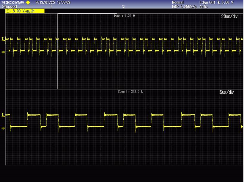
Here is the gate(Vgs) waveform. Is this correct operation or not?

and it looks the duty is limited to 50% around. 

BQ27530EVM: is not Charging Battery

$
0
0

Part Number:BQ27530EVM

Hi,

I am using BQ27530EVM with 3.7v 7800mAH ( Note : I am not using EV2400).

We have tried to power it from both  5V 2A power supply and with USB port and from the J2 input , both fuel gauge and charger is enabled on the board but the battery doesn't get charged.

Below is our Jumper settings:

1. JP5 is Charger enabled (ON)
2. JP4 is Gauge enabled (ON)
3. JP1 is installed 
4. JP3 is high enabled (for input on J2)

Kindly guide us.

Thanks
Yatish.M

Viewing all 35901 articles
Browse latest View live


<script src="https://jsc.adskeeper.com/r/s/rssing.com.1596347.js" async> </script>