BQ27510 abnormal RemainingCapacity working
HPA495 could not detect temperature probe
Hi,
I am currently using Bq20z90 v1.50 and am preparing it for mass production. Currently using the BQ multi station tester HPA495, and having issues with it not able to detect the temperature probe.
I have also tried the using the internal temperature probe but still the error comes out.
Any ideas on what went wrong?
bq27530 Gerber file
which will be suitable to instead BQ27500-V130
Hello:
I have used BQ27500-V130 to perform the faul gauge of the battery of my design, and almost finished my design now , but I got the information that this ic is now not recommanded in new design because it has been stopped production.
So I want to know which is suitable for us to instead BQ27500, our agency recommand that we used BQ27510-G3, but I cannot find it from the product tree of website of ti, I can find BQ27520-G4.
Can you give us some advice?
Thanks a lot.
bq27510 BI/TOUT
What is the voltage at TOUT (when it is pulled high) during temperature measurement?
BQ27510-G3 Life cycle?
Is the BQ27510drzr-g3 near the Not Recommended for New Design stage? I see 231 units available from Mouser, no other North American distributor is stocking it, and the similar G2 part is already NRND. Too bad because I designed it in to a new product a few months ago when it was readily in stock, no indication of end-of-life in the product information pages on the web site.
Any ideas on a replacement part? I refuse to use a BGA part on a safety critical device that receives shock and vibration stresses in normal use. Most of the newer Gas Gauge chips are in the BGA package, which makes them very tiny indeed but not suitable for my application.
bq769x0 VCn filter components
Datasheet states 100 min and 1k typical value for Rfilt on VCn inputs. There is no maximum value.
I believe Cc information is for the associated capacitor. Right?
EVM uses 1k with 1uF.
Would it be allright to use 3k and 330nF?
Cutoff frequency would stay much the same but I don't know if increasing resistor may introduce imprecision in the ADC stage...
Regards,
Frederic
BQ3050 RSOC Question
Hi,
My Name is David and I need to ask a TI engineer a question off of the public forum. It is in regards to our battery management system that uses a BQ3050 and it's non-linear RSOC performance below 20%.
Please excuse my brevity but I am not able to elaborate the question on this urgent issue for our commercial products until our conversation is private.
Thank you
BQ27621-G1 stops responding when the battery is replaced/reconnected
Hi,
BQ27621-G1 fuel gauge stops responding to I2C commands(NACKing!) when I disconnect and reconnect the battery. Also I observed I don't see 1.8V LDO output on VDD pin when it is not responding!
If I do power cycling gauge works fine. Can anyone comment on this issue? Since i cant stop the system during the battery replacement suggest me if there is procedure to follow to have robust system!
Thanks,
Shan
BQ78350 work without MCU
Hello,
We get a customer who wants to use BQ76940+BQ78350 to accomplish 15 cells monitor and protection.
Is that possible to work without MCU after configuring the setting by GUI ? Can BQ78350 monitor the voltage,current, temperature without communicating with MCU ?
Can BQ78350 + BQ76940 do cell balance without communicating with MCU ?
Thanks a lot !
Regards
William
bq34z100 High Pulse Current
I am using the bq34z100 for an application which has very occasional, extremely high, but short duration, pulse current loads on top of a more constant current profile. Would you be able to advise me which bq34z100 gas gauge settings would be most appropriate for an application like this.
Writing in the Manufacturer Info Block of bq27510-G2
Hi,
I had done multiple dfis before and was able to parse the bqfs to be included in the C# code for the programming at production phase.
As a last minute request of the client, they would want to redo the characterization and write the company name, dfi version and dfi generated date in the Manufacturing Block (A and B). Basically, i am hoping to write Company Incorporated V1 YYYY-MM-DD in the Manufacturer Block.
Question:
1. Can I modify the Manufacturer Block of an old DFI file and update it without having to go thru the learning process again? If yes, can anyone guide me on how i could do this?
2. If i have to perform the characterization again, (as there are some revisions in the hardware design), how can i write the data in the manufacturer block using EV2300 and bq EVSW? Would i have to write the hex value of the manufacturer block one by one in the Data Flash System Data tab? Should i do this before i update the Golden pack?
Thanks,
Kat
BQ77910A EVM
Dear TI support,
We aredesigning acircuit usingaBQ77910A.
In the datasheetsluu855,sparkgaphas beendescribed.Since wewant todesign asparkgapasESD protection,Could youtell methe layout of thegap?
BQ33100. Can't change flash values
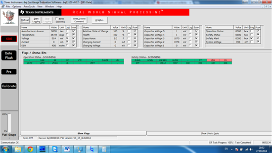
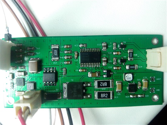
Hi. I made a supercap charger and trying to get it working. Currently i'm stuch trying to configure bq33100. This charger should be configured to use 2 series supercaps, internal temp sensor, stack balancing, max stack voltage 5.2v.
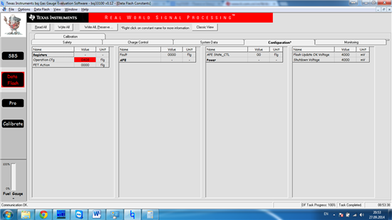
I'm using a TI BQ Gas Gauge Evaluation Software. Chip is unsealed. Actual battery pack voltage = 4400mv, input voltage before chg fet = 5200mv. When I'm trying to change Data Flash -> Configuration -> Opertion cfg from 0408 to 0101 I got red input box with old 0408 value.
I tried to export flash data to .gg file, change it and import back but after write all I got 0408 again. I downloaded bq33100 firmware, switched chip into ROM mode and flashed bq33100.senc (from TI site) but this didn't help.
I know that flash writes are disabled when stack voltage < Flash update OK voltage (=4000mv) and software shows stack voltage = 465mv. It looks like the problem is in calibration, but I couldn't clibrte it
Is there any way to get it configured ???
BQ34Z110 X10 scaling parameter (bit 7 of the Pack Configuration Register) effects
Question 1) I am confused by the description given on page 21 of the BQ34Z110 data sheet (Dec 2012) regarding the X10 MODE.
X10 MODE
The bq34z110 supports high current and high capacity batteries above 32.76 Amperes and 32.76 Ampere-Hours
by switching to a times-ten mode where currents and capacities are internally handled correctly, but various
reported units and configuration quantities are rescaled to tens of milliamps and tens of milliamp-hours. The need
for this is due to the standardization of a two byte data command having a maximum representation of ±32767.
When the X10 bit (Bit 7) is set in the Pack Configuration register, all of the mAh, cWh, and mWh settings will take
on a value of ten times normal. When this bit is set, the actual units for all capacity and energy parameters will
be 10 mAh or Wh. This includes reporting of Remaining Capacity. This bit will also be used to rescale the current
reporting to 10 times normal, up to ±327 A. The actual resolution then becomes 10 mA.
It is important to know that setting the X10 flag does not actually change anything in the operation of the gauge.
It serves as a notice to the host that the various reported values should be reinterpreted ten times higher. X10
Current measurement is achieved by calibrating the current gain to a value X10 lower than actually applied.
Because the flag has no actual effect, it can be used to represent other scaling values. See Design Energy
Scale.
If it is "various reported units and configuration quantities" please state specifically which are affected.
If it is "all" then please confirm that "all" the following data flash parameters are afffected.
BQ34Z110 mA and mAh parameters
Taper Current (mA)
Min Taper Capacity (0.01mAh)
Rem Cap Alarm (mAh)
Initial Standby (mA)
Initial Max Load (mA)
CC Threshold (mAh)
Design Capacity (mAh)
Design Energy (mAh) -- scaled by Design Energy Scale parameter
SOH Load Current (mA)
SOC1 Set Threshold (mAh)
SOC1 Clear Threshold (mAh)
SOCF Set Threshold (mAh)
SOCF Clear Threshold (mAh)
Max Lifetime Chg Current (mA)
Max Lifetime Dsg Current (mA)
Sleep Current (mA)
User Rate (mA)
User Rate (mW) -- scaled by Design Energy Scale parameter
Reserve Cap (mAh)
Reserve Energy (mWh) -- scaled by Design Energy Scale parameter
Qmax Max Delta % (mAh)
Dsg Current Threshold (mA)
Chg Current Threshold (mA)
Quit Current (mA)
Qmax Cell 0 (mAh)
Avg I Last Run (mA)
Avg P Last Run (mW) -- scaled by Design Energy Scale parameter
Deadband (mA)
Question 2) Also please expand on the function of the "T Rise" parameter also scaled by the Design Energy Scale setting (See Table 10, p17)
Thanks,
bq27510-g3 min value of the standby current
hello,
i'm involved in a design where the reporting of the remaining capacity of the used battery is vital. So i've decided for this purpose to use a system gas gauge bq27510-g3.
I've understood mostly the function of the chip but i'm in doubt with the measurement of the standby current, respectively with the min. value of it. When our device is in OFF state the current consumption is less than 1 mA (ca. 300uA) from the battery. Because the device can remain in this state for a long time of period (i.e. 2 or 3 months) this fact can not be leave unconsiderated. I saw in the datasheet that a "deadband" value can be set in a range from 0 to 255.
If i set the deadband value on "0", will the bq27510 measure the OFF state current flow correctly?
How is the right dealing actually with this behaviour?
Thanks in advance for your help.
Alexandru
Arduino BQ34Z110 / BQ34Z100 program to read and write flash
Hey,
here is a little program to access the dataflash with an arduino over I2C... I just used it with BQ34Z110 but it should work with BQ34Z100 as well but no guarantee for that. I could solve many problems by reading posts from this forum so it's just fair to give something back:
// Write flash to BQ34Z110 Gas Gauge Chip
// by Clemens Zange
#include <Wire.h> // Wire library for communicating over I2C
#define BQ34Z110 0x55 // I2C address of the BQ34Z110
#define voltageDeviderH 0x3d // 15180 mV in decimal is 0x3b4c in HEX to calibrate: NewVoltDiv=VoltDiv*VoltMess/VoltDisplayed
#define voltageDeviderL 0x8e
#define designCapH 0x05
#define designCapL 0xdc
#define designEnergyH 0x23
#define designEnergyL 0x28
#define packConfiRegH 0x09
#define packConfiRegL 0x70
#define ledChgReg B10001011
#define alertConfigRegH B11011011
#define alertConfigRegL B01100111
uint8_t flashbytes[32] = {0};
// BQ34Z110 flash Functions
// Reading the 32 Flashbytes of the subclass you enter
void readFlash(uint16_t subclass)
{
delay(300);
Wire.beginTransmission(BQ34Z110);
Wire.write(0x61);
Wire.write(0x00);
Wire.endTransmission();
Wire.beginTransmission(BQ34Z110);
Wire.write(0x3e);
Wire.write(subclass);
Wire.endTransmission();
Wire.beginTransmission(BQ34Z110);
Wire.write(0x3f);
Wire.write(0x00); // change this to 0x01 if offset is >31
Wire.endTransmission();
Serial.print("Flash: ");
for (int i = 0; i < 32; i++)
{
Wire.beginTransmission(BQ34Z110);
Wire.write(0x40+i);
Wire.endTransmission(false);
Wire.requestFrom(BQ34Z110,1);
flashbytes[i] = Wire.read();
//Serial.print(i);
//Serial.print(": ");
Serial.print(flashbytes[i],HEX);
Serial.print(" ");
}
Serial.println(" ");
delay(300);
}
void chgFlash(uint8_t index, int value)
{
// change flashbyte first
flashbytes[index] = value;
//flashbytes[1] = 0x60;
// write flashbyte
Wire.beginTransmission(BQ34Z110);
Wire.write(0x40 + index);
Wire.write(flashbytes[index]);
Wire.endTransmission();
/* Wire.beginTransmission(BQ34Z110);
Wire.write(0x41);
Wire.write(flashbytes[1]);
Wire.endTransmission();
*/
}
void checkSum()
{
//calc checksum
int chkSum = 0;
for (int i = 0; i < 32; i++)
{
chkSum += flashbytes[i];
}
//Serial.println(chkSum);
int chkSumTemp = chkSum / 256;
//Serial.println(chkSum);
chkSum = chkSum - (chkSumTemp * 256);
//Serial.println(chkSum);
chkSum = 255 - chkSum;
//Serial.println(chkSum);
//write checksum
Wire.beginTransmission(BQ34Z110);
Wire.write(0x60);
Wire.write(chkSum);
Wire.endTransmission();
}
void writeConfig()
{
//changing voltagedivider
Serial.print("Change voltagedivider to:");
Serial.print((voltageDeviderH<<8)+voltageDeviderL);
Serial.println("mV max");
readFlash(104);
chgFlash(14,voltageDeviderH);
chgFlash(15,voltageDeviderL);
checkSum();
delay(500);
readFlash(104);
//changing design capacity & energy
Serial.print("Change design capacity to:");
Serial.print((designCapH<<8)+designCapL);
Serial.print("mAh and design energy to:");
Serial.print((designEnergyH<<8)+designEnergyL);
Serial.println("mWh");
readFlash(48);
chgFlash(21,designCapH);
chgFlash(22,designCapL);
chgFlash(23,designEnergyH);
chgFlash(24,designEnergyL);
checkSum();
delay(500);
readFlash(48);
//changing pack configuration register & led charge indication & Alertconfig
Serial.println("Change pack config register to:");
Serial.println(packConfiRegH,BIN);
Serial.println(packConfiRegL,BIN);
Serial.println("Change LED charge indication register to:");
Serial.println(ledChgReg,BIN);
Serial.println("Change alert config register to:");
Serial.println(alertConfigRegH,BIN);
Serial.println(alertConfigRegL,BIN);
readFlash(64);
chgFlash(0,packConfiRegH);
chgFlash(1,packConfiRegL);
chgFlash(4,ledChgReg);
chgFlash(5,alertConfigRegH);
chgFlash(6,alertConfigRegL);
checkSum();
delay(500);
readFlash(64);
}
void readFlags()
{
Wire.beginTransmission(BQ34Z110);
Wire.write(0x0e);
Wire.endTransmission();
Wire.requestFrom(BQ34Z110,1);
Serial.println(Wire.read(),BIN);
Wire.beginTransmission(BQ34Z110);
Wire.write(0x0f);
Wire.endTransmission();
Wire.requestFrom(BQ34Z110,1);
Serial.println(Wire.read(),BIN);
}
void run_command(uint8_t command)
{
int readln = 0;
switch (command)
{
case 1:
Serial.println("Which flashregister do you want to read? Type subclass in DEC!"); // enter subclass decimal
while (Serial.available() <= 0)
{
}
readln = Serial.parseInt();
Serial.println(readln);
readFlash(readln);
delay(500);
break;
case 2:
Serial.println("Writing configuration...");
writeConfig();
break;
}
print_menu();
}
void print_menu()
{
Serial.println();
Serial.println("*******************Menu*******************");
Serial.println("Press 1 to read flash.");
Serial.println("Press 2 to write configuration.");
Serial.println();
}
void setup()
{
Serial.begin(9600);
Wire.begin();
print_menu();
}
void loop()
{
if (Serial.available()>0) // check for input
{
int user_command;
user_command = Serial.read()-48; // read command
//Serial.println(user_command);
run_command(user_command);
}
}
EC2300 and C#
Hi. I want to communicate with a battery via the EV2300 module, in C#. does anyone know how to do this? relatively new at c#, and it's been awhile since i programmed in visual basic. hoping there's a dll or something i can pull into my app.
BQ27421 Datasheet Clarification
MSP-TS430PN80USB and bq76PL536EVM-3
Hello,
I have the MSP430F5529 and bq76PL536EVM-3 modules and i'm trying to verify the cell balancing algorithm with 6 li-ion cells that are connected to the first battery connector as single operation ("Circuit 1" on the EVM). I compiled and downloaded the code provided following the guidelines on Application Report SLAA478, then made the power and communication connections between the MSP430 target board and bq76PL536EVM-3. I can see the SPI signals generated by bq76PL536EVM-3 on my oscilloscope, however cell-balancing doesn't work.
The system works normally when i use bq76PL536 Evaluation software v2.2 in stand-alone mode. What I need is to be able to accomplish cell-balancing without a computer.
Thank you.


