Quantcast
Channel: Power management forum - Recent Threads
Viewing all 35901 articles
Browse latest View live

LM5175: No pulses on HDRV2 in Boost Mode

$
0
0

Part Number:LM5175

Hi,

we have several designs built with LM5175 that are working very well. With one of these we got a new lot and have trouble with the free wheeling diode in parallel to the high Driver output FETs. Now I found that the Controller doesn't Output the gate Signal HDRV2  to the high Drivers whereas the LDRV2 is coming.The Output voltage (32V) is stable but all power is fed throug the Diode instead of the Transistors.  I changed the Controller as I suggested that it is defect but it is still the same. The amazing Thing is that it Outputs the Signals when I operate the Booster from a weak (24V) power supply and it stops outputting the Signal running with a strong (24V) supply. This behaviour is Independent of the Output power. We already have produced this board a couple of times running well so the design is working well.  From the new production lot I got the first 4 Units and all have the same behaviour.

What can the reason be that the LM5175 does not output the HDRV2 Signal?

Thanks for your help

Thomas

TPS62095: Current limit details

$
0
0

Part Number:TPS62095

Team,

Can you please help with details on the current limit functionality for TPS62095

• 7.4.3,  in the datasheet syas “Once the internal current limit is triggered 32 times…”. How long transients are required for triggering?

• Is the current limit trigger count restored after a certain time or only after restarting the controller?

• In the same chapter in the datasheet also says “… the device stops switching and starts a new start-up sequence after a typical delay time of 66μS passed by.” Does “start-up” also include soft start?

Thanks ,

Anders

WEBENCH® Tools/UCC256301: Can't find proper FETS

$
0
0

Part Number:UCC256301

Tool/software: WEBENCH® Design Tools

When I go to the webench tool from the product page for the UCC256301 using the default settings the tool returns an error saying it cannot find a suitable FET for the design and is using an ideal FET. Because of this there is no selection in the BOM to select a BOM for this design.  The real design I need to use is for 220VAC in and 48VDC @4A out.  How do I get the webench tool to give me a design that I can work with?

BQ34Z100EVM: Voltage Calibration Error

$
0
0

Part Number:BQ34Z100EVM

Hey, I calibrated the BQ34z100EVM for CC offset and board offset, and the calibration was successful. Then, I proceeded to voltage calibration, but its giving me an error saying: 'Calibration-A read of data written failed comparison.' The voltage I applied is 4 V. The gauge is also reading the voltage currently and the voltage divider is set at 5000 mV.

I have updated the EV2400 firmware and have the latest version of BQstudio running on my system. My jumpers are configured on <=5V, the default .srec file is loaded in the gauge, VOLSEL is green, Flash update OK cell voltage is 2.8 V, No. of series cells is 1. Why is this error occurring? Thanks!

LM25119Q: Thermal pad

$
0
0

Part Number:LM25119Q

Dear TI Experts,

I am now using LM25119 and find a problem needs your suggestion:

Input 12V output 5V ,but their is no output now~

I check my layout and find that the thermal pad of LM25119 is not connected to  GND, I'd like to know if it will affect the LM25119's function?

BQ24650: Maximum input current on STAT1 and STAT2 pins

$
0
0

Part Number:BQ24650

Hello,

In the datasheet, a 10k resistor is used with an LED on the STAT pins for notifications. We'd like to use a 1k resistor instead to increase the brightness on our LEDs.

The datasheet doesn't call out a maximum sink current for the STAT pins. We are using Vref as the source which is 3.3V, through a 1k resistor, which is 3.3mA load. 

Can the STAT pins sink 3.3mA of current?

Thanks,

Nick

TPS775: Parallel multiple TPS775 LDO Reg

EV2400: EV2400


BQ40Z50: Retrieving data from a fuel gauge

$
0
0

Part Number:BQ40Z50

Hi - 

I have a battery management system board using a BQ40Z50, I am trying to read the data in the fuel gauge using BQ studio and both an EV2300 and an EV2400, but I cannot access the fuel gauge. There are 8 connectors out of the PCB 9 pins out of the board, but none is labeled. Is there a fast/reliable way to read the fuel gauge directly? perhaps removing it and putting in on a TI box?

Any help is appreciated. 

Thanks

BQ76200: Pack voltage swings above Batt voltage at DSG FET turn-on

$
0
0

Part Number:BQ76200

Hello,

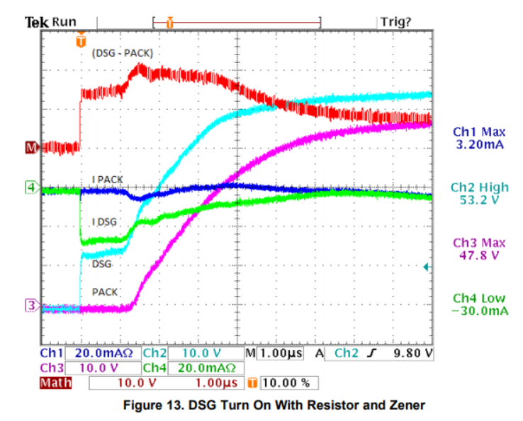
I am having an issue with a prototype design using a BQ76200 connected to a BQ76930.  While my CFET is turned ON, I toggle the DFET and capture the turn ON on the oscilloscope.  This was done similarly to what was shown in the "Beyond the Simple Application Schematic" in Figure 12 and Figure 13.  The only difference between the components used in those figures is that I also have TVS diodes across VGS of both FETs.  That being said, here is Figure 13 from that document:

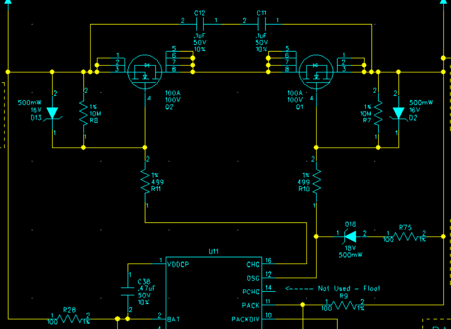
Here are the two that I took using a Power Supply and voltage divider to simulate a battery on the Input.  You can see what my voltage of the power supply is, so I wouldn't expect to see such a huge swing of voltage on the output at the turn-on of the FETs.

Here is a screenshot of my schematic:

Please let me know your feedback.

Thanks, Mike

TPS60400-Q1: Output Impedance with voltage below 1.8V

$
0
0

Part Number:TPS60400-Q1

Hello Team,

Do we have any information about what the output impedance of the TPS60400-Q1 looks like when the input voltage is below 1.8V?

The graph on page 7 of the datasheet seems to show it going to 35ohms and probably higher before the device is powered on.

I'm guessing from page 10 all the output transistors would be open in this state. Is that correct?

Best,

David

TPS92512: IC pops after a few seconds

$
0
0

Part Number:TPS92512

Hi!

I have been working on getting a 2A LED driver working using the TPS92512 IC for the past couple of weeks.

The circuit does function to some extent (it lights up the LEDs for some time and can be PWM dimmed), but after a short amount of time 5-60 seconds the IC pops/explodes and shorting pin 9 and 10. Often it also causes the PWM pin of my STM32 to stop working. This happens also when running at low current ( < 200mA) and PWM duty cycle.

Originally I used a 60V Schottky  diode for D301, which I was advised to upgrade to a 100V 3A Schottky. However this did not resolve my issue with the IC blowing up. I have now made a handful 4 layer PCBs with this which all have suffered from this. I have followed all PCB design guidelines and used high voltage capacitors/diodes. This happens for the HV and non-HV version of the IC.

Details:

  • The power is turned on over about 100ms to avoid any LC spikes from the input capacitor and power supply leads.
  • LED+ and LED- is connected to an array of 8 strings of 12 white LEDs in series - requiring about 36V to start lighting up.

Am I missing something and can I provide any extra information? (Photos, PCB layout)

TINA/Spice/LM5164: Start-up into heavy capacative load

$
0
0

Part Number:LM5164

Tool/software:TINA-TI or Spice Models

Hi,

I'm trying to model the effect of designing an LM5164 step down circuit when used with a large capacative load. Vin around 60V vout only 3.3V. The spice model you offer does not have thermal effects modelled and in the design I'm working on I have several thousands of uF of load capacitance. This causes the LM5164 to run up against its current limiters for several 10's of mS before it reaches the regulated output target voltage.

I understand that the LM5164 has over temp protection, but I don't wish to use this as normal operation. Is there any way that I can predict the temp of the device. Or to ask the question another way, how long can the LM5164 withstand being operated above its internal current limiter before I will see over temp protection kick in?

Thanks

Aidan

BQ34Z100-G1: how to create a .gg.csv file using Battery Management Studio

$
0
0

Part Number:BQ34Z100-G1

I am using "Battery Management Studio" version 1.3.86 and I want to submit a zip file for TI to ID a battery chemistry. 

For example this link has instructions on how to create the zip file:

http://www.ti.com/tool/GPCCHEM

I got a reply back from TI when I submitted a zip file with the following error:

"Required file 'gg.csv' is missing from the input zip file."

I could not find where in the "Battery Management Studio" software version 1.3.86 to go to create a .gg.csv file.

The instructions say to

1) program the chem ID

2) Export <name>.gg file or <name>gg.csv file

Can someone point me to how to export the .gg.csv file using Battery Management Studio?

Thanks,

Doug

TPS62110: TPS62110

$
0
0

Part Number:TPS62110

The data sheet recommends teh resister R3 to be 1Mohm between the output and PG (Pin 13). How could PG behave if R3 = 2.2k?


LM5017: LM5017 failure mode - "VIN" pin burning and melting package/PCB trace

$
0
0

Part Number:LM5017

Hello,

I seem to be having a similar issue to this post from 2013, however I haven't been able to get a hold of him to ask if his fix worked:

https://e2e.ti.com/support/power-management/f/196/t/273008

I have had 6 LM5017 chips fail so far in the same manner.

I have an LM5017 powered off 44-51V and its output is connected to the primary coil of a transformer to give 3 isolated 14V outputs. This is for a 3-phase motor drive application and the outputs are powering TI UCC27211 high/low side gate drivers.

The motor drive works for for the most part, but every now and then (I don't know how to replicate the failure) the LM5017 will just pop and we will see a hole in the package near the VIN pin or the pin burned off. This only happens on a "start" condition when the gates begin to switch/FETs begin to turn on. The last one was bad enough to actually delaminate the 1oz trace on our PCB!


Has anyone had a similar failure with this part or is there an applications engineer for this part that can shed some light on what events cause this type of failure? 

Thanks,

Vishaal

BQ24161: how to program the bq24161 battery charger.

$
0
0

Part Number:BQ24161

Hello,

Hi. I have studied the datasheet and I know that I need to program the chip using I2C bus . How do I access the registers inside the chip? I have seen examples on youtube in which a program written in c does the job.

The end goal is to design my own pcb board using Diptrac but I do need to program the chip so that it can work with a lithium ion battery.

Thanks in advance!

Naimesh

LM2937-3.3: Output capacitor polarity reversed?

$
0
0

Part Number: LM2937-3.3


Hi, 

In Figure 22 of the datasheet, is the Cout polarity reversed? Or is that intentional? 

BQ24735: Altium file

$
0
0

Part Number:BQ24735

Is there any Altium schematic/layout files for this device?

TPS43061: Altium file

$
0
0

Part Number:TPS43061

Is there any Altium schematic/layout files for this device?

Viewing all 35901 articles
Browse latest View live


<script src="https://jsc.adskeeper.com/r/s/rssing.com.1596347.js" async> </script>