Quantcast
Channel: Power management forum - Recent Threads
Viewing all 35901 articles
Browse latest View live

TPS65735: Max Lswitching speed possible, ability to drive 4 shutters instead of 2 and any leads on shutter suppliers and shutter type info?

$
0
0

Part Number:TPS65735

Hello, I have several questions regarding the TPS65735 PMIC.

We have an unusual design where we need to control 4 LCD shutter at once, not two.

I would like to know:

1) What switching speeds are possible? I would ideally want to control the LCD shutter at 240Hz rate, not the typical 120.

2) Can two TPS65735 be synced together to drive 4 LCD shutters instead of 2, each transparent only 1/240th of a second? If not, what alternative options are there?

3) Can you provide any leads on Asian suppliers/manufacturers of such LCD shutters? Do the LCDs have to be twisted nematic, thin nematic or ECB? It's almost impossible to find this info. I am certain they don't have to be expensive pi-cell due to the price of existing shutter glasses.  Direct message me if you can't post that info in the forums.

Thank you.


Win10 can't link to battery management studio

$
0
0

OS: Windows 10 Enterprise

Software: Install EV2300 

When DUT connect battery and also link to PC, Battery Management Studio can't show battery information.

Is there any step I miss? 

TPS60403: Switching frequency issue at shorted between -5V and GND.

$
0
0

Part Number:TPS60403

Hi

Customer have a issue the switching frequency issue at shorted between -5V and GND.

Please refer the following waveform.

Switching frequency = 323.8kHz

Superimposed frequency = 52.63kHz

Could you please let me know about the reason of this strange frequency?

The datasheet doesn't descript about short protection.

Muk

TINA/Spice/LM5155: TINA ref design or SPICE model

$
0
0

Part Number:LM5155

Tool/software:TINA-TI or Spice Models

Hi
It seems importing the SPICE model of LM5155 fails in TINA.
Is there a way to have a ref design or at least a spice model of LM5155 that could run in TINA ?
Thanks

LM5116: LM5116: testing on actual board

$
0
0

Part Number:LM5116

hi ,

in continuation to the post & schematic shared & the verification & the suggestions by TI , my customer has made the PCB board .

below are the testing results :


 we have concluded with the following.


1) UVLO on the LM5116 is somehow not working, so we used the ENABLE pin to shutdown device.

2) TLV1701 pin-out is wrong on our board. Although TLV3401 pin-out matches. So used TLV3401 and tested ENABLE pin.

it works okay.

3) With a 47uH inductor, there is a small but noticeable audible hum.

4) We tested with 2A and around 3.5A current at 14.8V. It works satisfactorily.

5) Our BMS solution works good in series with the charger.


So currently am unable to resolve #1 and #3


BQ24250: BQ24250 INPUT VOLTAGE BASED DPM

$
0
0

Part Number:BQ24250

For our battery pack product we are using BQ24250 IC. This IC have EN1, EN2 pins for controlling charge current. If we use this IC in our battery pack and set EN1=1, EN2=0 then ILIM is set by external resistor.

We will set ILIM to 1A and set ICHARGE to 900 mA. The battery pack will have USB input port but only VCC and GND pins are used. (D+ and D- enumeration lines will not be used).


We will select VDPM=4.36V.

1)  In this case battery pack can work with universal charger adaptor, with  source current more than 1A. So battery pack will get charged with all universal charger.


2)  If we connect battery pack to PC. The USB port of PC will source 500 mA of current (since only supply pins are connected and no D+/D- pins connected), in this case ICHARGE is 900 mA, and Isource= 500 mA, so the USB voltage will drop down below 4.3V. If USB voltage is below 4.3V then input current limit falls down to prevent drop in supply voltage (DATASHEET PAGE 27). In such case what will be the range for adjusted current limit value? Will it be below 500 mA? if user used this IC in similar fashion will there be any degrade to IC?

TPS62160: Please help recommend that the function is similar to TPS62160, IQ needs less than 1uA

$
0
0

Part Number:TPS62160

Hi ,

  1. Please help recommend that the function is similar to TPS62160, but the static power consumption is too high, IQ needs less than 1uA;           
  2. TPS62160 supplies power to other peripherals. In order to save power, many MOS are added to the input. As shown in the figure, if there is a low power consumption, this part of the device can be saved. Can you recommend a solution for me?

Thanks

BRs

Elsa Duan

Please recommend it- RS485+ADC+Power

$
0
0

Hi 

1. The power supply I am looking for in the official network is this tps54231 input voltage 4.5V-28V output voltage 3.3-5V output maximum current 1.5A can be used.           

2. 10M Rate of RS485 3V3 Power Supply           

3. AD Conversion Chip Industrial Electronic Scale Applied 3V3 Power Supply 24 Bits

Thanks 

BRs

Elsa Duan


BQ27510-G3: BQ27510-G3 and BQ40Z60 question

$
0
0

Part Number:BQ27510-G3

Hi,

There is a question from our customer:

The limit on BQ27510-G3 and BQ40Z60 is that TI BQ has certain algorithm to evaluate the cell decay over time, but Qmax’s and Ra table update will not happen under below conditions:

Depth of discharge(DoD)is less than 37%.

Temperature is out of the range of 10C-40C.

However, in our application temperature is usually above 40C and depth of discharge is less than 5%. So this type of battery management controller is not suitable for our application.

Could you help to find out other BMC?

TPS2511: Connection with two Usb ports

$
0
0

Part Number:TPS2511

Hello
We have a product that has two usb ports and we are thinking to use two TPS2511. But what if we use only one control charger with two usb ports in parallel connected with data line + and -. What problems can we have if in usb ports we try to charge two phones in the same time, or else.

Thank you.

UCC28C41-Q1: Minimum on time of UCC28C41

$
0
0

Part Number:UCC28C41-Q1

hello,

I want know the minimum on time of UCC28C41. Because the I find the drive of UCC28C41 at high voltage and Light load have a fixed turn-on time (73ns). Therefore, I want to know why.

Thank you very much!

LM5155: How much current is it output at 200Vdc?

$
0
0

Part Number:LM5155

Hi team.

I'd like to use LM5155 to drive the piezo element.

Piezo will be driven at 200Vdc.

How much current is LM5155 output in our usecase?

And then I think that 200V booster circuit can not be configured at 24V input.

So, I'm planning of a configuration like a fig44 in data sheet p.31 . 

How much current does this configuration assume(fig.44)?

Could you give me some advice.

Sincerely.

Kengo

TPS92691: Ferrite beads filter for high current

$
0
0

Part Number:TPS92691

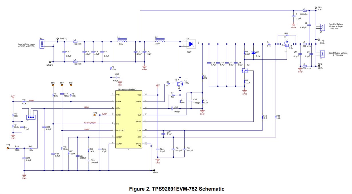
In the EVM datasheet schematic, two input beads and 2 output beads are used.

In my application, I drive 56V 5A COB LED. Input voltage is 22-50V, so input current can be ~6-13A. I read on Internet, that beads saturate and lose their filtering efficiency, so, it is better to use beads with current ratings 3-4 times higher. How can I implement such filter, as in the example in the datasheet? There are no ferrite beads with current ratings higher than 10A.

CCS/UCD3138: About WRITE program checksum

$
0
0

Part Number:UCD3138

Tool/software: Code Composer Studio

After I do "WRITE program checksum" , This message was desplayed.

What does this message mean?  What kind of causes can you think of?

BQ24030: USB and Solar Charger with Power Path (BQ24030 / BQ2407x vs. BQ24210 or MCP73871)

$
0
0

Part Number:BQ24030

I am designing a sensor node running off a single cell Li-ion battery (1S1P). The battery should be chargeable from a solar panel and USB.

For everything solar the BQ24210 seems to be the go-to IC, because of it's MPPT-like ability to limit the current drawn from the solar panel when it drops beneath a certain threshold. The MCP73871 from Microchip seems to have a similar feature (proudly explained by Adafruit) and used to be my favorite choice because it also implements something like a Power Path, allowing the charger to reduce the charge/discharge cycles with a proper charge termination (so the claim). Whereas a the BQ24210 only charges the battery without knowing how the system load interferes with it. Am I correct so far?

But now I discovered the BQ24030 and the BQ2407x-family with exactly the same claim. Furthermore it reads "The DPPM circuit reduces the charge current when the input current limit causes the system output to fall to the DPPM threshold". Is that not just the same as the MPPT-like behavior of the BQ24210/MCP73871? If yes, what are the disadvantages against the much younger, and apparently more popular BQ24210?

For the BQ2407x this DPPM threshold is 4.3 V, while the DPM threshold is 4.5 V? That is a bit confusing.

And while I lean towards the BQ24030 (because of the dual input) what would be a good setting for this threshold to charge a standard INR18650 with a run-of-the-mill 5...6 V panel? A standard 39k resistor would give me almost 4.5 V, which should be pretty close to the maximum point of power.


UC3843: 1000V 10W Flyback SMPS design calculations

$
0
0

Part Number:UC3843

I am trying to design a 1000V,10W output flyback-SMPS with 12VDC input and frequency 100KHz using IC3843. I had initially used the WeBench tool to get the values of the circuit components. However, after wiring the hardware, the circuit didn't work. After days of debugging and consulting TI engineers, I found out that most of the values output by the tool were incorrect. So, I have decided to calculate all values using the IC's datasheet. Most of the values have straight forward calculations. However, I found some calculations to be ambiguous. 

To calculate Cct, tdeadtime = 2.83us, by graph in Fig.9 (page 10), Cct is coming out to be 10nF
and from equation fosc = 1.72/(Rrt*Cct) Rrt is coming out to be 1720 Ohm. But Rrt should be >= 5K. So how do I calculate the correct value of Rrt?  

Apart from that, for the calculation of Rcsf, the value of Rramp is required. To calculate the value of Rramp the only info given is "Choose the value of RRAMP to be much larger than the RRT resistor so that it does not load down the internal oscillator and result in a frequency shift." Is that the only binding condition?

Lastly, how to calculate the value of Ccsf?

BQ24650: Battery not charging

$
0
0

Part Number:BQ24650

Hi!

We've been trying to use the BQ24650as the charger for a lead acid battery, as you can check on the schematic. We followed the slva437a application for a 1.6A charge current

Our voltages are as follow:

VCC: 23.97V

VFB: 1.8V

SRN: 12.73V

MPPSET: 1.54V

STAT1: 23V

STAT2: 17V

VTS: 1.9V

REGN: 6V

VREF: 3.29V

And this is what it looks like on the battery side:

Could you please help us?

TPS53353: Why the LL pins will not output sometime?

$
0
0

Part Number:TPS53353

Dears:

Could you kindly help to check the below schematic?

Since sometime(CPU process some channels' video) the pins of LL will not output, and after about 2.3ms LLs will be OK. However, the CPU is in crash state.

Why the LL pins will not output sometime?

CCS/UCD3138A64OEVM-662: Program does not run when I disconnect the target power source and reconnect it.

$
0
0

Part Number:UCD3138A64OEVM-662

Tool/software: Code Composer Studio

I have UCD3138A64 module with me, every time before i burn the code using CCS I clear the flash memory and than load the desired code, during burning the code it shows writing in flash at certain range of address and Performing Flash Program on certain memory range. But when i disconnect the power source and reconnect it , the program does not run.

Does this imply that the code is present in the RAM and not in the flash ?

P.S I even used the sample codes provided in training labs but still i get the same error. Please reply fast .

TPS84250: External Output Capacitance max spec

$
0
0

Part Number:TPS84250

Posting for a customer:

In the datasheets for the TPS84250 and TPS84259 there is a specification for a max external output capacitance of 430uF. Due to system design requirements (to minimize bus fluctuation due to load variation) our customer would like to have lots of capacitance on this line (greater than 430uF).


What is driving this specification?  Is it due to inrush current?

Is there any way around the spec so our customer can have additional output capacitance?


Thanks!

Viewing all 35901 articles
Browse latest View live


<script src="https://jsc.adskeeper.com/r/s/rssing.com.1596347.js" async> </script>