↧
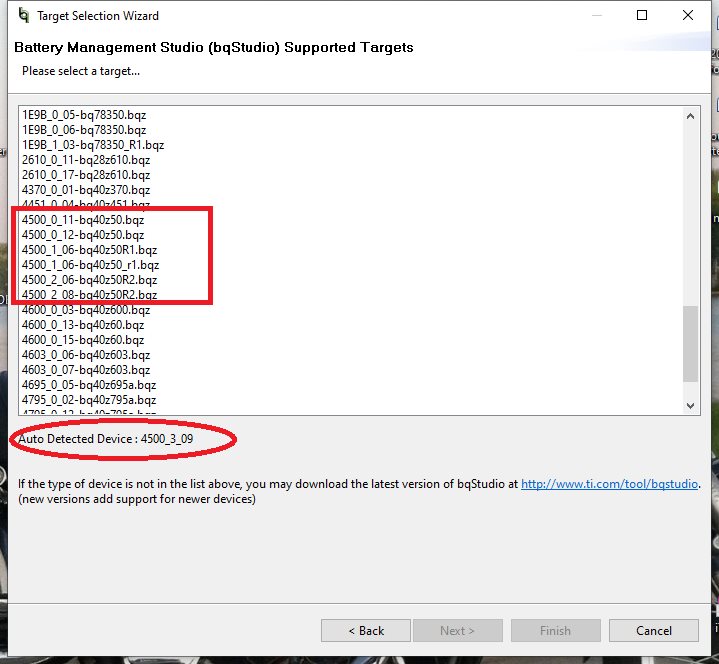
BQ40Z50-R3-DEVICE-FW: BqStudio does not recognize firmwareR3
↧
LM117: rad-hard LDO with an Enable pin
Part Number: LM117
Hi,
Does TI have a rad-hard LDO with an Enable pin?
I need three different voltages and of course could use three of the same part number adjustable LDO's.
1. Input voltage 5V, output voltage 3.3 volts, max output current 100 mA.
2. Input voltage 5V, output voltage 1.8 volts, max output current 100 mA.
3. Input voltage 5V, output voltage 1.25 volts, max output current 100 mA.
↧
↧
CSD13385F5: MOSFET basics: how come this FET only has unidirectional gate-source diode?
Part Number: CSD13385F5
Hi,
I am rather used to seeing bi-directional diodes (like two Zeners facing each other) between gate and source in MOSFETs. However, this part has a uni-directional diode.
1) How come?
2) In what way would you say I should take this into consideration when selecting whether to use this part? In this case I am planning to use this nFET to switch on/off a high-side pFET (grounding/not grounding its gate) acting as a load switch.
Thanks!
↧
CSD13385F5: Would need unencrypted SPICE models
Part Number: CSD13385F5
Hi,
We are considering to use CSD13385F5 in combination with CSD22204W. However, we would need unencrypted SPICE models to first verify that the design idea works in detail.
Could you please instruct us on how get a hold of these two models?
Thanks!
↧
TPS63020: Power save mode output voltage rising
Part Number: TPS63020
Hi Team,
When using TPS63020, i have below 3 questions need your help:
1."During the power save mode, the output voltage is monitored with a comparator by the threshold comp low and comp high" As i noticed on datasheet, in light load, the output voltage would be 2.5%-3.5% above the normal output. What is the reason that we design like this and what need to care for customer use under this condition?

2.How to understand "The maximum average current in the switches is limited to a typical value of 4 A", in different output current?
3.When Vin=Vout, would the device shrift from buck to boost mode frequenctly, would this bring some noise for EMI performance?
Best Regards,
Gene
↧
↧
BQ25570: How to measure the impedance of the bq25570?
Part Number: BQ25570
How to measure the impedance of the bq25570 when it is working?
By R=V/I?
↧
BQ25886: Charging Status Indicator blinking
Part Number: BQ25886
Hello Experts,
We are using BQ25886 and has question of Charging Status Indicator blinking.
In the BQ25886 datasheet 8.3.8.2 Charging Status Indicator, it is shown that blinking at 1Hz.
But sometimes the blinking happens at around 5Hz and we do not know the reason.
Do you know why and which condition will let STAT pin blinking frequency faster than 1Hz?
In our testing, it might happens when Vbus drop at 4.3-4.5V
(using USB Type A cable > 1 meter)
Thank you.
HsinYu Lin
↧
BQ24192I: Input current is large without battery
Part Number: BQ24192I
Hi Jeff,
As we have discussed here
https://e2e.ti.com/support/power-management/f/196/t/845657
Improper values of switching inductor and output capacitors will cause large input current of about 30mA when there is no battery being charged.
As the datasheet says, To get good loop stability, the resonant frequency of the output inductor and output capacitor should be designed between 15 kHz and 25 kHz. With 2.2-µH inductor, the typical output capacitor value is 20 µF.
Now in my design, I use 1uH+44uF, but sometimes the current is about 30mA, could you help to investigate further to explain such situation?
Thanks.
↧
TPS62125: EN_HYS pin used as Low Battery Indicator while step-down is still enabled
Part Number: TPS62125
Hi all,
TPS62125 (powered with a 16.5V battery and configured for V_OUT=3.3V) has a PG pin to test output voltage but no Low Battery Indicator (LBI). As I have very tough space and target price constraints I cannot use a separate voltage detector (e.g. TPS3710) to test if nominal battery voltage (16.5V) falls below a predefined threshold (e.g. 15V).
It seems anyway that EN_YS pin could be used as an LBI, As described on the datasheet it is an open-drain and is pulled to GND when 'voltage on the EN pin is below the comparator threshold V_TH_EN_ON of typ. 1.2 V'. In particular 'The pin is pulled to GND once the falling voltage on the EN pin trips the threshold V_TH_EN_OFF (1.15 V typical)'.
So, if I connect EN pin to V_IN through a 1.2M resistor and to GND through a 100k rsistor, I expect that EN_HYS pin (simply pulled-up to 3.3V with a 20kohm resistor) is pulled to GND whenever V_IN falls below 15V, working as an LBI (of course while TPS62125 is still enabled and continues to regulate). Is this correct or cannot it work like this for some other reason?
Many hanks in advance.
Best regards,
Mauro
↧
↧
BQ4050: registers meaning
Part Number: BQ4050
Hi,
what is the meaning of the next registers which appears at the main GUI screen:
1) CEDV RC
2) discharge cap
3)cedv threshold
4)cedv fit
5)charge deficit
thank you for your help!
Victor.
↧
BQ40Z50-R1: bq40z50-r1 Short circuit double pulse problem
Part Number: BQ40Z50-R1
Hello to TI support team ,
I have problem with additional pulse from discharge pin bq during short circuit connection at battery output .(according to scope figure )
I tried different parameters set for short circuit threshold 1 & 2 . RSNS '1' and RSNS '0' .
1. Sometimes additional short pulse appear during short permanent short circuit and sometimes at first short contact .
B.R
Alex Burtakov
↧
SM72445: Operation when connected to a fixed DC input voltage
Part Number: SM72445
I have an application which requires a variable solar cell input boosted to a fixed 48VDC output voltage, and was thinking of using the SM72445. The solar cell input may optionally be fed by a fixed 12VDC voltage. In this case it still needs to be boosted to 48VDC. Can the SM72445 operate with a fixed 12VDC input? Is panel mode involved as the conversion ration is 1:4?
↧
UCC27211: PWM Tina Simulation Question
Part Number: UCC27211
Hello,
I am fairly new to Tina. I am currently trying to simulate a Full-bridge DC/DC converter using two-half bridge GD, UCC27211. The expected output is Vo = 30V and Io = 3 A. Would I need single PWM controller or would the piecewise linear signals possible. (Please visit the site to view this file)
↧
↧
EV2400: USB reset fail
Part Number: EV2400
Hello,
I've tried to use EV2400 on my linux machine via Windows in Virtualbox. It seems like the EV2400 can't handle USB reset and dies, until being physically reconnected.
[26883.579055] usb 1-1.2: new full-speed USB device number 58 using ehci-pci
[26883.680096] usb 1-1.2: New USB device found, idVendor=0451, idProduct=0037, bcdDevice= 0.12
[26883.680100] usb 1-1.2: New USB device strings: Mfr=1, Product=2, SerialNumber=3
[26883.680102] usb 1-1.2: Product: EV2400
[26883.680104] usb 1-1.2: Manufacturer: Texas Instruments
[26883.680105] usb 1-1.2: SerialNumber: F7BA1B5108002500
[26883.682966] hid-generic 0003:0451:0037.0021: hiddev2,hidraw5: USB HID v1.01 Device [Texas Instruments EV2400] on usb-0000:00:1a.0-1.2/input0

Here, Virtualbox requested revice reset...

[26906.388492] usb 1-1.2: reset full-speed USB device number 58 using ehci-pci
[26906.461812] usb 1-1.2: device descriptor read/64, error -32
[26906.641826] usb 1-1.2: device descriptor read/64, error -32
[26906.821794] usb 1-1.2: reset full-speed USB device number 58 using ehci-pci
[26906.898502] usb 1-1.2: device descriptor read/64, error -32
[26907.078457] usb 1-1.2: device descriptor read/64, error -32
[26907.261803] usb 1-1.2: reset full-speed USB device number 58 using ehci-pci
[26907.678445] usb 1-1.2: device not accepting address 58, error -32
[26907.751761] usb 1-1.2: reset full-speed USB device number 58 using ehci-pci
[26908.168447] usb 1-1.2: device not accepting address 58, error -32
[26908.169620] usb 1-1.2: USB disconnect, device number 58
[26908.241777] usb 1-1.2: new full-speed USB device number 59 using ehci-pci
[26908.315081] usb 1-1.2: device descriptor read/64, error -32
[26908.495075] usb 1-1.2: device descriptor read/64, error -32
[26908.675085] usb 1-1.2: new full-speed USB device number 60 using ehci-pci
[26908.748449] usb 1-1.2: device descriptor read/64, error -32
[26908.931741] usb 1-1.2: device descriptor read/64, error -32
[26909.038749] usb 1-1-port2: attempt power cycle
[26909.635078] usb 1-1.2: new full-speed USB device number 61 using ehci-pci
[26910.048403] usb 1-1.2: device not accepting address 61, error -32
[26910.121744] usb 1-1.2: new full-speed USB device number 62 using ehci-pci
[26910.535070] usb 1-1.2: device not accepting address 62, error -32
[26910.535449] usb 1-1-port2: unable to enumerate USB device
Same thing happens, when I Try to reset device manually. Other USB devices work without problems even with Virtualbox.
So, it boils down to some USB implementation bug in EV2400.
Same problem reported on Virtualbox forums. Anybody else encountered similar problems?
↧
LM25116: 36 to 24V converter incorrect output: board review
Part Number: LM25116
Hello,
We are undergraduate students on an engineering project team. We are trying to build a 36V to 24V converter that can take 36-42V input and output 24V at a max current output of 8A.
We have created a board that currently outputs about 18.5V, and drops significantly as the resistance of the connected load increases. We are unsure whether this is due to manufacturing issues or design flaws of the board.
We have attached the Altium schematic and PCB layout for the board below; we would really appreciate if you could review our design and help us troubleshoot our issues.
Thank you!
(Please visit the site to view this file)
↧
BQ34Z100-G1: FlasjStream file with more than 32 bytes data in string
Part Number: BQ34Z100-G1
Hello,
I use direct I2C communication between the BQ34Z100-G1 fuel gauge IC and microcontroller, which act as I2C master.
Unfortunately I have not the EV2300/EV2400 device, and at this time I have no possiabilites to buy it.
I read a lot of documentation and information about the IC, from Texas Instruments and from this forum.
At present time, I can communicate with the IC by I2C protocol.
I can send and get results for the commands, the extended commands, read flash data and write flash data into the IC, without EV2300/EV2400 and bqStudio.
But!
Now I need to write the df.fs file (FlashStream) to the IC.
The file I received from my friend who have the EV2400 device and EVM with BQ34Z100-G1 on board.
He created the golden image for my battery, and send FlashStream files to me. And I want to write the data from the FlashStream file into IC.
But I can not understand the discrepancies between the contents of FlashStream file and the C code from the SLUA801 document.
The discrepancies in the fact, that the gauge_execute_fs function writes 32 bytes of data only, from each string
of the FlashStream file, to the IC, and the rest of the data, in the string, the function simply throw out.
The gauge_execute_fs function C code locate on pages 13 and 14, in SLUA801 document.
But FlashStream file (.df.fs) contain W: strings, with mush more than 32 bytes data in strings.
Moreover .bq.fs contain a lot W: strings, with more than 32 bytes data.
And, as I see, first short strings (commands) from FlashStream file switching the IC into ROM mode.
My questions is:
Can I write entire data, more than 32 bytes, from FlashStream file string, into BQ34Z100-G1 when it in ROM mode ?
Is it will error or not ?
Thank in advance.
Dmytro
↧
BQ25886: bq25886 issue
Part Number: BQ25886
When enable charge but battery is not connected. The waveform of bq25886 seems strange. The time axis is 40us. Why the SW switches for about 20us then stops for about 120us and repeat again? It may not be a charge and recharge process. Because the Deglitch time for recharge threshold and charge termination is about 250ms. It also may not be PFM. Because PFM at light load when battery is below minimum system voltage setting or charging is disabled. I watch the register. There is no fault and the charging state is CC fast charging. The Vsys and Vbat increases as charge voltage limit increases.

↧
↧
LM5122: LM5122 PMP10886 schematic question
Part Number: LM5122
Hi Support team
may i know the function of following circuit R1?

↧
UCC28C44: Looking for alternative PWM controller
Part Number: UCC28C44
Dear expert,
I'm looking for PWM controller, and found UCC28C44, it's performance and feature could meet my requirment, but it's operating temperature is -40'C~105'C.
I'd like a device that the operating temperature could be -40'C ~ 125'C,package size is VSSOP (8) 3.00 mm × 3.00 mm or smaller, and other performance are similar with UCC28C44, can you share some recommendations?
↧
TPS51916: about TPS51916's power-up
Part Number: TPS51916
How to contorl TPS51916's power-up ,because we use it power our cpu at the same time, but our cpu has a power-up sequence.
thanks very much!
↧