Quantcast
Channel: Power management forum - Recent Threads
Viewing all 35901 articles
Browse latest View live

BQ27542-G1: BQ27542-G1 Chem ID selection tool

$
0
0

Part Number:BQ27542-G1

Dear TI Engineer,

We are using BQ27542-G1 chip and BQ studio for  battery Chem ID selection which customized by ATL company. I performed a data collection followed by the GPC instruction and uploaded data to the TI data upload website. I have 2 questions about the GPC report from TI by email.

1. Are these Chem ID listed from all existing fuel gauge chips chemistry, but not only one chip?  Can I just use  one of the IDs directly for my new  battery?

2. Below fuel gauge is just an example to tell me how to choose best chem ID, is that right?  For Example, I see the ID 3640 in the recommend list in the GPC report, so, I can use BQ27542-G1 with the Chem ID 3640 as my new battery ID?

(Please visit the site to view this file)

Thank you very much

Mike

TL431B-Q1: Reference Voltage Specification

$
0
0

Part Number:TL431B-Q1

Dear, Sir. 

I got several failure from my customer. The cause would be lying on their side due to 

miss-operation during testing process. 

We observed Anode voltage is about 20V higher than Reference voltage. So that, 

We are assuming it would be the cause failure. 

However, the reference voltage specification is not clear on the datasheet. 

Please give your advice for the clarification as followings. 

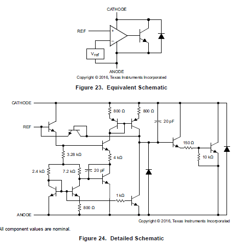
1. Test circuit as Figure 20, Anode =GND & Reference voltage is respect to Anode = GND. 

    The other side, the Schematic as Figure 24, it looks Reference voltage should be higher

    a certain level than Anode voltage. 

    Is it no problem when Anode voltage is 20V higher than Reference voltage?

2. If above had a problem, Could you please clarify the reference voltage specification

    to avoid the failure. 

Best Regards, 

H. Sakai

BQ25601: Solar Powered Operated WSN Node

$
0
0

Part Number:BQ25601

hi,

I need to verify my design, that i'm working on, A Remote WSN node which will be powered by a Renewable Energy Source like Solar, and the Solar Panel Specs are as follows

Vmp=+6v

VOC=+11V

Imp=0.5A

Pmax=3.5W

I have selected BQ2601 as the charger IC for my Li+ion Battery 18650 type, requirements are mostly met with ours, And a Boost convertor like TPS63070 is used to power other sensors

Which will work at greater than +3.3V, I'm very keen to know that, Is this the Best approach of mine?, Or any  Best practices are suggestible which can be adopted into my design.(Please visit the site to view this file)

LMR14030: LMR14030SDDAR

$
0
0

Part Number:LMR14030

Dear Sir/Madam,

I am using LMR14030SDDAR in my product, which is a OBD2 complaint vehicle diagnostic tool. In one of our customer location there was a power supply issue being reported and we at our test location found that the LMR14030SDDAR regulator was damaged, also 3A fuse was also damaged. The 3A fuse is placed at the input of the power supply section. I am generating 5V using this regulator. The 5V is also powering 2 nos CAN FD ICs. The CAN ICs are also damaged.

Can you please let me know the possible reasons for the damage of the output of the regulator IC ?

This has become a big issue and my top management is asking if this issue will appear on all boards that are already in customer sites. There are approximately 5K devices with our customers.

TPS23861: TPS23861 IC getting failed in radiated immunity testing.

$
0
0

Part Number:TPS23861

Hi TI support,

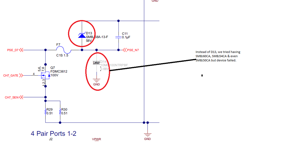
We recently used TPS23861PW in one of our projects & found IC is getting damaged in radiated immunity testing even with 15V/m of filed intensity while rest electronics of the product works well. Some of the comments as below for your information,

=> We are testing radiated immunity by attaching cables on PoE port (our EUT is PSE) but peripheral/ PD is not attached at other end of cable. This replicates the actual field scenario.

=> We found device getting damaged with 30V/m, 20V/m & even 15V/m in both vertical & horizontal antenna orientations in frequency range of 80MHz to 1GHz. 90% AM modulation was used with 1KHz sine wave, dwell time was 1sec & 1% step increase was used. We even tried manipulating protection diode values upto SMBJ50CA but didn't succeed.

=> We analyzed 3 units & all were found TPS23861 getting damaged, rest all components in PoE section were intact. Replacing TPS23861 made all EUT functional.

=> We are using core PoE circuit as in evaluation board only difference is we are using protection diode from drain of FET to GND instead of drain to 48V. Please see attached section.

=> We are using fixed 48V SMPS in our EUT & independent magnetic from Wurth electronics. I can provide schematics on getting some email ID.

Please look into this urgently.

Regards,

jagdish

TPS25940: SGS report

$
0
0

Part Number:TPS25940

please help to share me the SGS report for

please help to share us the sgs repor for

SN74AUP2G07DRYR

TPS51362: TPS51362 temperature range question and LP# function

$
0
0

Part Number:TPS51362

Dear Sir,

I am Alec form Taiwan. MY customer is currently using TPS51362 and they have two question needed you kindly hlep:

1. the Temperature range: in the latest spec, it shows TPS51362 operating range is -10~85(please see the first pic below). However, in the early spec, it shows it can support -40~85 temperature range(please see the sec figure below ). And RD wish is it this part for the  -40~85 design spec for their new project. Therefore, we would like to check you with if we could still suggest RD using TPS51362 with -40~85 temperature range? Please kinldy let us know

2. About LP# function, it is used to control TPS51362 into ULQ™ Mode with 100uA low-bias current. RD is wondering that what is the power status of TPS51362 with it is in this mode. what is status for Vout? and Vref? please kindly let us know

Above, please kindly give us some advice and we are looking forward to hear from you soon. thanks in advance

Alec

TPS61195: The behavior when the Vin exceed the abs max

$
0
0

Part Number:TPS61195

Hi team,

Could you advice me how TPS61195 behaves when the Vin exceeds the absolute maximum( = 24V)?

I'm appreciate if you could tell me about the typical failure mode when the Vin violates the abs max.

Regards,

Saito


TPS61180: Operation after current limitation reaches without FET at Fault

$
0
0

Part Number:TPS61180

Hi all

Would you mind if we ask TPS61180?

<Question1>
We would like to confirm the operation after current limitation reaches without FET at Fault.
There are descriptions on the datasheet as follows;
"The TPS61180/1/2 family has pulse by pulse over-current limit of 1.5A (min).
 The PWM switch turns off when the inductor current reaches this current threshold.
 The PWM switch remains off until the beginning of the next switching cycle.
 This protects the IC and external component under over-load conditions.
 When there is sustained over-current condition for more than 16ms ( under 100% dimming duty cycle),
 the IC turns off and requires PER or the EN pin toggling to restart."
So, in case of without FET at Fault, does the device operation(PWM) stop after current limitation also?
However, without FET at Fault, the current flows from IN to OUT.

<Question2>
In relation to <Question1>,
 The PWM switch turns off when the inductor current reaches this current threshold.
 The PWM switch remains off until the beginning of the next switching cycle.
 This protects the IC and external component under over-load conditions.
 When there is sustained over-current condition for more than 16ms ( under 100% dimming duty cycle)
->We would like to confirm the detail operation,
   the inductor current reaches this current threshold -> next switching cycle -> switch on at instant -> switch off -> next switching cycle -> switch on at instant -> switch off ->・・・・・ repeating it during 16ms,
   the device will shut down, right? Is our recognition correct? 

Kind regards,

Hirotaka Matsumoto

UCC2897A: Output Unstable

$
0
0

Part Number:UCC2897A

Dear Team,

Here is my previous thread, but I didn't receive a further suggestion from your team. So I create a new thread.

Please take a look of the attached waveform for Vgs and Rsense.

It trips the 0.5V threshold so the Vout didn't regulate at 12V.

They modify the Rsense from 150m to 40m, but it will have audible noise during low load.

Do you have a further suggestion on it?

BTW, is 20uH acceptable here? Because we don't have suitable calculation tool here to check the suitable parameter.

BR

Kevin

Linux/TPS65217: Not able to reboot the device (Custom AM335x based board)

$
0
0

Part Number:TPS65217

Tool/software: Linux

Hi,

I was facing some issue related to the reboot of the device.

It was like, when I issue poweroff command from linux, the device gets powered off,

and when I issue reboot command then also the device gets powered off but doesn't reboot.

For your infomation,

  • I am using a custom AM335x based board, with TPS65217 as the secondary PMIC and there is a primary PMIC which mainly act as buck-boost converter.
  • The primary PMIC controls the TPS65217, by disabling or making ENABLE pin of Primary PMIC as low, the TPS65217 would be switched off.
  • The only way to turn on the device now is by making the ENABLE pin of Primary PMIC go HIGH.

BQ77915EVM-014: Fault Protection Test Result is different from datasheet.

$
0
0

Part Number:BQ77915EVM-014

Hello,

Customer tests fault protection with BQ77915EVM.

But its test result is different from datasheet as below.

Tested both condition of  5 Cells (1 EVM) and 10 Cells (2 EVM)

Used Power Supply for CHG and Electric Load for DSG.

Could you let me know why test result is different from datasheet description?

Regards,

Nicky

TPS2388: If i want to change the sense resistor as per the 802.3af standard?

$
0
0

Part Number:TPS2388

Hi ,

Thanks for your reply.

as per TPS2388 EVM the sense resistor assign for 802.3at standard. If i want to connect the 802.3af device, I need to change sense resistor as per the 802.3af standard?

or the same design can comfortable with 802.3af standard including over current detection?

LP5036: Bi-direction LED connection

$
0
0

Part Number:LP5036

Hello

                 Could LP5036 support below connection topology? Thank you. 


BR

Patrick

TPS40055: Simulation tool

$
0
0

Part Number:TPS40055

Hi team,

The customer is considering using TPS40055 for below requirements, but it seems there is no simulation model in Webench for this part. Could you provide any simulation tools for TPS40055? And also, could you let us know if you have any other recommended part for the requirements?

Requirements;

- Input voltage: 24V+/-10%

- Output voltage: 12V

- Output current: 5A(max)

- Ta: 55degC (Air-cooling is not expected by FAN for CPU)

- Use-case: Power supply for PC mother-board

Please let us know about the simulation tool for TPS40055, and other recommended parts if you have?

Regards,

Jun


LM20146: Sw frequency

$
0
0

Part Number:LM20146

Our customer has a question about SW frequency of LM20146.

They use 260kohms as RT.

Fsw 247.62kHz  is given from EQ(8) in datasheet P16.

If this frequency set about 200kHz, what kind of problem happen ?

TPS62826: Thermal Information

$
0
0

Part Number:TPS62826

Hi

My Customer has question.


Customers are considering adopting the TPS62826.


The TPS62826 data sheet describes two thermal resistances.
Why is the value of θJa significantly different between JEDEC and EVM?

Also, when carrying out evaluation on a JEDEC board, do you have Via etc. on the board?

Regard

T Kishi

UCC28180: UCC28180 EMI & efficiency optimization

$
0
0

Part Number:UCC28180

Hello,

Could you give some suggestion on UCC28180 EMI & Efficiency optimization, below is description, thank you.

Input 220-480, output 600W
Input 220-277, output 480W
Input 1802-480, output 1200W
Input 220-277, output 1400W
At present, the frequency band that conducts EN55015 10M-20M is NG. The inductor uses magnetic ring inductance, iron silicon aluminum.
During low voltage input, the efficiency suffered.

Does TI have High-Voltage-Buck controller like NP101A or VIPER12A for Smart Home Products?

$
0
0

Does TI have  High-Voltage-Buck controller like NP101A or VIPER12A for Smart Home Products(AC220V input and Low DC voltage output)? It requires very low standby power consumption that current is uA-level?

LM1085: May LM1085 can work in Vin 24V and Vout 20V 2A condition?

$
0
0

Part Number:LM1085

Hi Sir 

May LM1085 can work in Vin 24V and Vout 20V 2A condition?

I check datasheet, it should be ok. but i can't run in webench.

if LM1085 can't be work. may we have other LDO can suggest?(customer need LDO because it will power to Amp)

                                               Bogey

Viewing all 35901 articles
Browse latest View live


<script src="https://jsc.adskeeper.com/r/s/rssing.com.1596347.js" async> </script>